-
Notifications
You must be signed in to change notification settings - Fork 0
/
1030008.md.bak
582 lines (396 loc) · 22.5 KB
/
1030008.md.bak
1
2
3
4
5
6
7
8
9
10
11
12
13
14
15
16
17
18
19
20
21
22
23
24
25
26
27
28
29
30
31
32
33
34
35
36
37
38
39
40
41
42
43
44
45
46
47
48
49
50
51
52
53
54
55
56
57
58
59
60
61
62
63
64
65
66
67
68
69
70
71
72
73
74
75
76
77
78
79
80
81
82
83
84
85
86
87
88
89
90
91
92
93
94
95
96
97
98
99
100
101
102
103
104
105
106
107
108
109
110
111
112
113
114
115
116
117
118
119
120
121
122
123
124
125
126
127
128
129
130
131
132
133
134
135
136
137
138
139
140
141
142
143
144
145
146
147
148
149
150
151
152
153
154
155
156
157
158
159
160
161
162
163
164
165
166
167
168
169
170
171
172
173
174
175
176
177
178
179
180
181
182
183
184
185
186
187
188
189
190
191
192
193
194
195
196
197
198
199
200
201
202
203
204
205
206
207
208
209
210
211
212
213
214
215
216
217
218
219
220
221
222
223
224
225
226
227
228
229
230
231
232
233
234
235
236
237
238
239
240
241
242
243
244
245
246
247
248
249
250
251
252
253
254
255
256
257
258
259
260
261
262
263
264
265
266
267
268
269
270
271
272
273
274
275
276
277
278
279
280
281
282
283
284
285
286
287
288
289
290
291
292
293
294
295
296
297
298
299
300
301
302
303
304
305
306
307
308
309
310
311
312
313
314
315
316
317
318
319
320
321
322
323
324
325
326
327
328
329
330
331
332
333
334
335
336
337
338
339
340
341
342
343
344
345
346
347
348
349
350
351
352
353
354
355
356
357
358
359
360
361
362
363
364
365
366
367
368
369
370
371
372
373
374
375
376
377
378
379
380
381
382
383
384
385
386
387
388
389
390
391
392
393
394
395
396
397
398
399
400
401
402
403
404
405
406
407
408
409
410
411
412
413
414
415
416
417
418
419
420
421
422
423
424
425
426
427
428
429
430
431
432
433
434
435
436
437
438
439
440
441
442
443
444
445
446
447
448
449
450
451
452
453
454
455
456
457
458
459
460
461
462
463
464
465
466
467
468
469
470
471
472
473
474
475
476
477
478
479
480
481
482
483
484
485
486
487
488
489
490
491
492
493
494
495
496
497
498
499
500
501
502
503
504
505
506
507
508
509
510
511
512
513
514
515
516
517
518
519
520
521
522
523
524
525
526
527
528
529
530
531
532
533
534
535
536
537
538
539
540
541
542
543
544
545
546
547
548
549
550
551
552
553
554
555
556
557
558
559
560
561
562
563
564
565
566
567
568
569
570
571
572
573
574
575
576
577
578
579
580
581
---
sku: 1030008
name: CANBed - Arduino CAN Bus Dev Kit
---
## ***Introduction***
--------------------------
[](https://www.longan-labs.cc/1030008.html)
[Docs in PDF](https://github.com/Longan-Labs/Hardware_CANBed_Series/raw/master/CANbed.pdf)
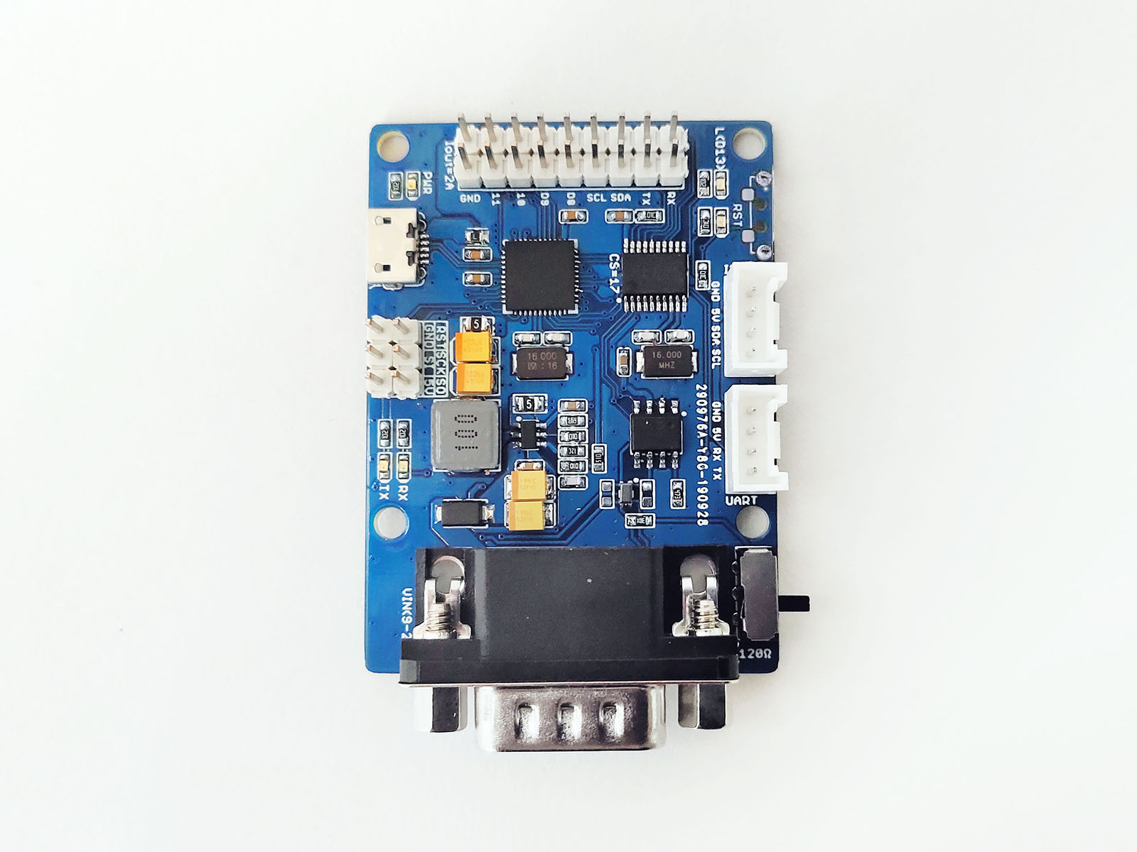
CANBed V1 is a CAN Bus dev board with Atmega32U4 microcontroller inside, which has **32KB** of Flash and **2.5KB** of RAM. The operating frequency is **16MHz**, which can meet most embedded applications. There's **Arduino Leonardo bootloader** inside the **Atmega32U4**. If you have used the Arduino IDE, programming will not be a problem for you. You can also use AVR Studio for development, we provide ICSP interface.
CANBed V1 uses **MCP2515** as CAN controller and **MCP2551** as CAN receiver, chich are high-performance CAN Bus chip, work at CAN 2.0 protocols. There is a Micro USB connector on the board, through which you can program the board or supply power to the board.There are one I2C, one UART, one SPI interface, 3 analog input interfaces and 8 digital IO on the board.
We use a flexible way for CAN interface. You can use 4PIN Terminal or DB9 connector. DB9 connector uses OBD-II mode by default. You can also configure CAN Open mode on the hardware. The voltage input range of the CAN interface is 9-28V, which can provide a stable 5V/1A output.
If you want to use this board to develop OBD related applications, click to get a [DB9 to OBD-II cable](https://www.longan-labs.cc/2020011.html).
!!!Note
For transportation considerations, the plug-in components of the kit are not soldered by default. After you receive the kit, you need to do some soldering work. If necessary, you can also contact [email protected] after purchasing the board, then we can send it to you after the board is soldered well.
!!!Note
Influenced by the price of the chip, we will frequently modify the product in the recent year, including the package of Atmega32U4 and the power chip. This will not affect the performance of the circuit board, please use it with confidence.
### Version Track
V1.0: Initial version
V1.1:
* Change package of Atmega32U4 from MU to AU
* Change package of the 16M crystal SMD5032 to DIP
V1.2:
* Change package of Atmega32U4 from AU to MU
* Change package of the 16M crystal from DIP to SMD3215
V1.2c:
* There are two packages for Atmega32U4 on the PCB, AU and MU packages, chich is selectively used during production. You may receive AU or MU version. The difference is only the packages of Atmega32U4, functions and performance are exactly the same. Please don't worry about it.
### ***Application Ideas***
With CANBed FD, you can,
1. To learn CAN Bus communication
2. To build product prototypes. After you complete the product prototype, we can help you integrate it into a product and assist you in production
3. To read the data from the car
4. As a part of your product, you don't need to design the MCU and CAN Bus separately, only need to complete other hardware design
### ***CANBed Family***
Currently we have 6 CANBeds, you can choose the right one according to your needs.
|**VRESION**|CANBed V1|CANBed FD|CANBed M0|CANBed M4|CANBed RP2040|CANBed Dual|
|--|---------|---------|---------|---------|----|-----|
|**MCU**|Atmega32U4|Atmega32U4|ATSAMD21G18|ATSAME51G19A|RP2040|RP2040|
|**CORE**|AVR 8 bit|AVR 8 bit|ARM Cortex M0+ 32bit|ARM Cortex M4 32bit|Dual ARM Cortex-M0+|Dual ARM Cortex-M0+|
|**PROTOCOL**|CAN2.0|CANFD & CAN2.0|CAN2.0|CANFD & CAN2.0|CAN2.0|CANFD & CAN2.0|
|**CLOCK**|16MHz|16MHz|48MHz|133MHz|133MHz|133MHz|
|**FLASH**|32KB|32KB|256KB|2MKB|2MKB|2MKB|
|**RAM**|2.5KB|2.5KB|32KB|192KB|264KB|264KB|
|**PRICE**|$24.9|$24.9|$24.9|$24.9|$15.9|$24.9|
|**LINK**|[GET ONE](https://www.longan-labs.cc/1030008.html)|[GET ONE](https://www.longan-labs.cc/1030009.html)|[GET ONE](https://www.longan-labs.cc/1030014.html)|[GET ONE](https://www.longan-labs.cc/1030013.html)|[GET ONE](https://www.longan-labs.cc/1030018.html)|[GET ONE](https://www.longan-labs.cc/1030019.html)|
## ***CAN BUS PRODUCTS LIST OF LONGAN LABS***
--------------------------
[](https://www.longan-labs.cc/blog/post/can-bus-product-summary/)
Logan-Labs have manufactured many different Can-Bus products. You can get more information through the following list, and choose a suitable product.
|PRODUCT NAME|LINK|PRICE|MCU|CHIP|PROTOCOL|
|------------|----|-----|---|----|--------|
|Serial CAN Bus Module|[LINK](https://www.longan-labs.cc/1030001.html)|$19.9|ATMEGA168PA|MCP2515|CAN2.0|
|I2C CAN Bus Module|[LINK](https://www.longan-labs.cc/1030017.html)|$19.9|ATMEGA168PA|MCP2515|CAN2.0|
|OBD-II Serial CAN Bus Dev Kit|[LINK](https://www.longan-labs.cc/1030002.html)|$20.9|ATMEGA168PA|MCP2515|CAN2.0|
|OBD-II CAN Bus GPS Dev Kit|[LINK](https://www.longan-labs.cc/1030003.html)|$29.9|ATMEGA32U4|MCP2515|CAN2.0|
|OBD-II CAN Bus Basic Dev Kit|[LINK](https://www.longan-labs.cc/1030007.html)|$24.9|ATMEGA32U4|MCP2515|CAN2.0|
|CAN-FD Shield|[LINK](https://www.longan-labs.cc/1030012.html)|$12.9|NO MCU|MCP2517FD|CAN-FD|
|CAN Bus Shield|[LINK](https://www.longan-labs.cc/1030016.html)|$5.9|NO MCU|MCP2515|CAN2.0|
|CANBed|[LINK](https://www.longan-labs.cc/1030008.html)|$24.9|ATMEGA32U4|MCP2515|CAN2.0|
|CANBed-FD|[LINK](https://www.longan-labs.cc/1030009.html)|$19.9|ATMEGA32U4|MCP2517FD|CAN-FD|
|CANBed M0|[LINK](https://www.longan-labs.cc/1030014.html)|$24.9|ATSAMD21|MCP2515|CAN2.0|
|CANBed M4|[LINK](https://www.longan-labs.cc/1030013.html)|$19.9|ATSAME51|-|CAN-FD|
|OBD-II RF Dev Kit|[LINK](https://www.longan-labs.cc/1030015.html)|$19.9|ATmega168PA|MCP2515|CAN2.0|
## ***Features***
--------------------------

* Implements CAN V2.0B at up to 1 Mb/s
* Industrial standard 9 pin sub-D connector or 4PIN Terminal.
* OBD-II and CAN standard pinout selectable at sub-D connector
* 2x4Pin Connector compatable with Grove system from Seeedstudio
* SPI Interface up to 10 MHz
* Standard (11 bit) and extended (29 bit) data and remote frames
* Power input from 9-28V
## ***Specifications***
--------------------------
Parameter|Value
---|---
MCU| Atmega32U4<br>(with Arduino Leonardo bootloader)
Clock Speed| 16MHz
Flash Memory|32KB
SRAM|2.5KB
EERROM|1KB
Operate Voltage| 9-28V
Output Current @ 5V | 1A
Input Interface | sub-D
## ***Hardware Overview***
--------------------------
### Part List
!!!Note
For transportation considerations, the plug-in components of the kit are not soldered by default. After you receive the kit, you need to do some soldering work. If necessary, you can also contact [email protected] after purchasing the board, then we can send it to you after the board is soldered well.
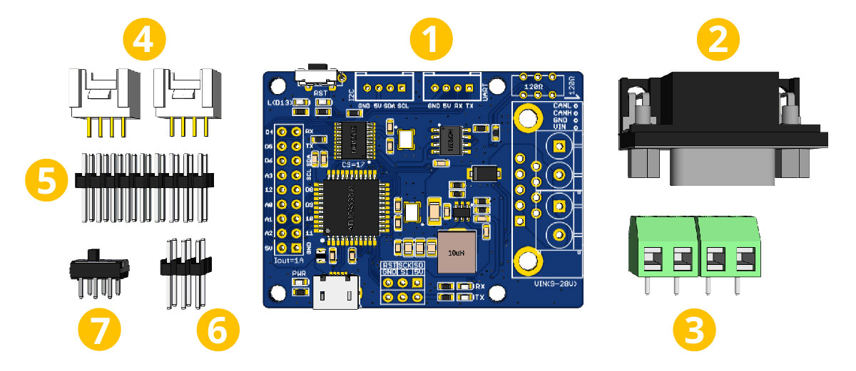
1. CANBed PCBA
2. sub-D connector
3. 4PIN Terminal
4. 4PIN HY2.0 Connector x 2
5. 9x2 2.54 Header x 1
6. 3x3 2.54 Header x 1
7. Switch for 120Ω terminal resistor
### Pin out
[](https://www.longan-labs.cc/media/wysiwyg/CAN-Bus/CANBed/Details_of_CANBed-01.png)
!!!Note
[Click](https://www.longan-labs.cc/media/wysiwyg/CAN-Bus/CANBed/Details_of_CANBed-01.png) to get larger image.
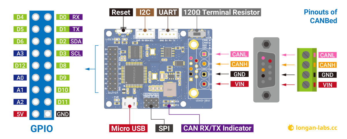
**1. GPIO - 9x2 I/O Pin OUT:**
The I/O of Atmega32U4 is list out here, which is consist of,
* 1 x UART (Serial1)
* 1 x I2C
* 4 x Analog Input(can be used us Digital IO)
* 8 x Digital I/O
**2. Micro USB connector for programming**
If you use Arduino IDE program the board, you need a micro USB cable to connect the board to PC.
**3. SPI - ICSP connector**
If you use AVR Studio to program the board, you can use this ICSP connector, and it can be used as SPI interface.
**4. CAN RX/TX Indicator**
When CAN Bus is transmitting data, these two leds blink.
**5. DB9 connector or Terminal for CAN Bus**
**6. Switch for the 120Ω terminal resistor for CAN Bus**
<p style="text-align:center"><img src="https://github.com/Longan-Labs/OBD-II_Slaver_GPS_kit/raw/master/HS_CAN_Termination.gif" /></p>
If you use this board on the end of the CAN bus, please put this switch to 120Ω. For more detail about the CAN bus protocol, please refer to the
[NI CAN Physical Layer and Termination Guide](http://www.ni.com/white-paper/9759/en/)
**7. Grove connector for UART**
Use Serial1 in the code
**8.Grove connector for I2C**
**9. Reset**
Click to reset the board.
## ***DB9 connector***
The DB9 interface of CAN Bus has two different protocols, OBD and CAN Open. Their definition is as follows,
|pin#|OBD(default)|CAN OPEN|
|----|----|-----------|
|1|GND|N.C|
|2|GND|CAN_L|
|3|CANH|GND|
|4|N.C|N.C|
|5|CANL|GND|
|6|N.C|N.C|
|7|N.C|CAN_H|
|8|N.C|N.C|
|9|CAN_V+|CAN_V+|
If you want to use the OBD protocol, you don't need to make any changes to the hardware.
If you need to use the CAN Open protocol, first we look at the back side of the PCB board, you can see the Pads below,
!!! Note
The picture shows another board, but it doesn't matter, the operation method is the same.
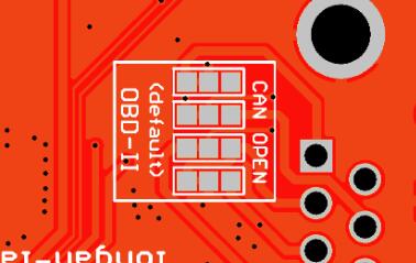
These pads are connected to the OBD side by default. We have to prepare a knife to disconnect the OBD side, and then use an electric soldering iron to solder the CAN Open side of the pads.

## ***Getting Started***
--------------------------
Here we use the Arduino IDE as a demonstration, through this chapter you can learn how to get started with CANBed.
You need a micro USB cable to connect the CANBed FD Dev board to the computer.
### ***IDE and Driver***
There's Arduino leonardo bootloader in the board.
Click to get the [latest Arduino IDE](https://www.arduino.cc/en/Main/Software).
There's Arduino Leonardo driver in the folder: Arduino/drivers.
### ***Download the install the library***
[Click](https://github.com/Longan-Labs/Aruino_CAN_BUS_MCP2515/archive/refs/heads/master.zip) to get the Arduino Library for CANBed FD Dev board.
In the Arduino IDE, navigate to Sketch > Include Library > Add .ZIP Library to install the Library.
### ***Open the code and upload it to the board***
Open the Arduino IDE, here we open the ***send*** example. This example can continuously send data to the CAN Bus.
```Arduino
#include <mcp_can.h>
#include <SPI.h>
const int SPI_CS_PIN = 17; // CANBed V1
// const int SPI_CS_PIN = 3; // CANBed M0
// const int SPI_CS_PIN = 9; // CAN Bus Shield
MCP_CAN CAN(SPI_CS_PIN); // Set CS pin
void setup()
{
Serial.begin(115200);
while(!Serial);
// below code need for OBD-II GPS Dev Kit
// pinMode(A3, OUTPUT);
// digitalWrite(A3, HIGH);
while (CAN_OK != CAN.begin(CAN_500KBPS)) // init can bus : baudrate = 500k
{
Serial.println("CAN BUS FAIL!");
delay(100);
}
Serial.println("CAN BUS OK!");
}
unsigned char stmp[8] = {0, 1, 2, 3, 4, 5, 6, 7};
void loop()
{
CAN.sendMsgBuf(0x00, 0, 8, stmp);
delay(100); // send data per 100ms
}
// END FILE
```
You need to select ***Arduino Leonardo*** on the Arduino IDE boards and select the correct COM port. Then you can upload the program to the CANBed FD Dev board by pressing the Upolading button on Arduino IDE.
## ***Get data from a Vehicle***
We can use CANBed to get data from a vehicle, we take the vehicle speed for an example here.
You can use our products to read data from cars. Here we provide a simple example by which you can read the speed and revs from a car. This is the [OBD-based PIDs protocol](https://en.wikipedia.org/wiki/OBD-II_PIDs). Regarding the deeper technology of OBD, we can't provide support at present. You may need to have some understanding of the car's protocol. After all, we are more of a hardware supplier.
The interface of OBD is as follows,
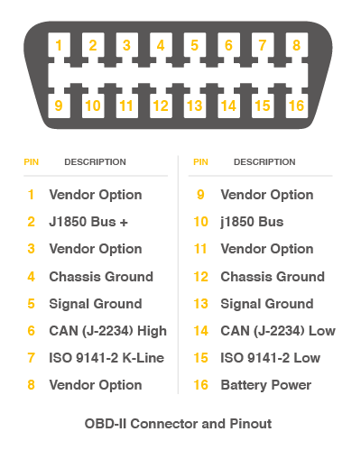
There're 4 pins we need to connect.
|OBD Pin|CANBed PIN|
|-------|----------|
|5. Signal Ground|GND|
|6. CAN(J-2234) High|CANH|
|14. CAN(J-2234) Low|CANL|
|16. Battery Power|VIN|
You can also use our [OBD-II to DB9 Cable](https://www.longan-labs.cc/2020011.html), which is very convenient to connect to OBD.
Upload the following code to the development board, then open the serial monitor, you get the speed from the car now.
```Arduino
#include <SPI.h>
#include "mcp_can.h"
/* Please modify SPI_CS_PIN to adapt to different baords.
CANBed V1 - 17
CANBed M0 - 3
CAN Bus Shield - 9
CANBed 2040 - 9
CANBed Dual - 9
OBD-2G Dev Kit - 9
Hud Dev Kit - 9
*/
#define SPI_CS_PIN 9
MCP_CAN CAN(SPI_CS_PIN); // Set CS pin
#define PID_ENGIN_PRM 0x0C
#define PID_VEHICLE_SPEED 0x0D
#define PID_COOLANT_TEMP 0x05
#define CAN_ID_PID 0x7DF
void set_mask_filt()
{
// set mask, set both the mask to 0x3ff
CAN.init_Mask(0, 0, 0x7FC);
CAN.init_Mask(1, 0, 0x7FC);
// set filter, we can receive id from 0x04 ~ 0x09
CAN.init_Filt(0, 0, 0x7E8);
CAN.init_Filt(1, 0, 0x7E8);
CAN.init_Filt(2, 0, 0x7E8);
CAN.init_Filt(3, 0, 0x7E8);
CAN.init_Filt(4, 0, 0x7E8);
CAN.init_Filt(5, 0, 0x7E8);
}
void sendPid(unsigned char __pid) {
unsigned char tmp[8] = {0x02, 0x01, __pid, 0, 0, 0, 0, 0};
CAN.sendMsgBuf(CAN_ID_PID, 0, 8, tmp);
}
bool getSpeed(int *s)
{
sendPid(PID_VEHICLE_SPEED);
unsigned long __timeout = millis();
while(millis()-__timeout < 1000) // 1s time out
{
unsigned char len = 0;
unsigned char buf[8];
if (CAN_MSGAVAIL == CAN.checkReceive()) { // check if get data
CAN.readMsgBuf(&len, buf); // read data, len: data length, buf: data buf
if(buf[1] == 0x41)
{
*s = buf[3];
return 1;
}
}
}
return 0;
}
void setup() {
Serial.begin(115200);
while(!Serial);
// below code need for OBD-II GPS Dev Kit
// pinMode(A3, OUTPUT);
// digitalWrite(A3, HIGH);
while (CAN_OK != CAN.begin(CAN_500KBPS)) { // init can bus : baudrate = 500k
Serial.println("CAN init fail, retry...");
delay(100);
}
Serial.println("CAN init ok!");
set_mask_filt();
}
void loop() {
int __speed = 0;
int ret = getSpeed(&__speed);
if(ret)
{
Serial.print("Vehicle Speed: ");
Serial.print(__speed);
Serial.println(" kmh");
}
delay(500);
}
// END FILE
```
If you want to get other data by PIDs, you can refer to the above example, and refer to [this link](https://en.wikipedia.org/wiki/OBD-II_PIDs)
## ***Arduino Code***
---------------------
We provide an [Arduino library for CANBed](https://github.com/Longan-Labs/CANBed).
!!!Note
Please change the SPI_CS_PIN to 17 for CANBed V1
There're many examples for the library, which is consist of,
* ***OBDII-PIDs*** - Get data from OBD-II interface
* ***send*** - Send a frame to CAN Bus
* ***recv*** - Receive a frame from CAN Bus
* ***set_mask_filter_recv*** - Receive a frame from CAN Bus with mask and filter setting
## ***APIs***
--------------------------
### 1. Set the Baud rate
This function is used to initialize the baud rate of the CAN Bus system.
The available baud rates are listed as follows:
#define CAN_5KBPS 1
#define CAN_10KBPS 2
#define CAN_20KBPS 3
#define CAN_25KBPS 4
#define CAN_31K25BPS 5
#define CAN_33KBPS 6
#define CAN_40KBPS 7
#define CAN_50KBPS 8
#define CAN_80KBPS 9
#define CAN_83K3BPS 10
#define CAN_95KBPS 11
#define CAN_100KBPS 12
#define CAN_125KBPS 13
#define CAN_200KBPS 14
#define CAN_250KBPS 15
#define CAN_500KBPS 16
#define CAN_666kbps 17
#define CAN_1000KBPS 18
### 2. Set Receive Mask and Filter
There are **2** receive mask registers and **5** filter registers on the controller chip that guarantee you getting data from the target device. They are useful especially in a large network consisting of numerous nodes.
We provide two functions for you to utilize these mask and filter registers. They are:
**Mask:**
init_Mask(unsigned char num, unsigned char ext, unsigned char ulData);
**Filter:**
init_Filt(unsigned char num, unsigned char ext, unsigned char ulData);
- **num** represents which register to use. You can fill 0 or 1 for mask and 0 to 5 for filter.
- **ext** represents the status of the frame. 0 means it's a mask or filter for a standard frame. 1 means it's for a extended frame.
- **ulData** represents the content of the mask of filter.
###3. Check Receive
The MCP2515 can operate in either a polled mode, where the software checks for a received frame, or using additional pins to signal that a frame has been received or transmit completed.
Use the following function to poll for received frames.
INT8U MCP_CAN::checkReceive(void);
The function will return 1 if a frame arrives, and 0 if nothing arrives.
###4. Get CAN ID
When some data arrive, you can use the following function to get the CAN ID of the "send" node.
INT32U MCP_CAN::getCanId(void)
###5. Send a frame
CAN.sendMsgBuf(INT8U id, INT8U ext, INT8U len, data_buf);
It is a function to send data onto the bus. In which:
* **id** ID of can frame.
* **ext** represents the status of the frame. '0' means standard frame. '1' means extended frame.
* **len** represents the length of this frame.
* **data_buf** is the content of this message.
For example, In the 'send' example, we have:
unsigned char stmp[8] = {0, 1, 2, 3, 4, 5, 6, 7};
CAN.sendMsgBuf(0x00, 0, 8, stmp); //send out the message 'stmp' to the bus and tell other devices this is a standard frame from 0x00.
###6. Receive a frame
The following function is used to receive data on the 'receive' node:
CAN.readMsgBuf(unsigned char len, unsigned char buf);
In conditions that masks and filters have been set. This function can only get frames that meet the requirements of masks and filters.
* **len** represents the data length.
* **buf** is where you store the data.
## ***FAQ***
--------------------------
!!!tip "I can't upload code to CANBed"
* When the board is connected to the computer via the Micro USB cable, a new COM device will appear on the computer. If the new device does not appear on your computer, you can try a different USB cable or try another computer.
* If your PC recognize the COM port, please try pressing the reset button, then click on the Upload button in Arduino IDE, when the IDE shows compile done, release the reset button immediately.*
!!!tip "The RX/TX led light up and never turn off"
* Check if the baudrate of CAN Bus is setting correct
* Try turning on/off the switch for the 120Ω terminal resistor
* Check if CANH and CANL is well connected, H to H and L to L
!!!tip "How to find the tech support"
Please contact [email protected] for technical support. Our technical support engineer will usually reply you within 24 hours on working days. In order to get faster support, we hope that when you send us an email, you need to include at least the following content,
* When and how to buy the product
* Product version information
* Take a high-definition picture of the product you use, including the connection
* Describe in detail the problem you encountered and what kind of help you would like to get
## ***Schematic Online Viewer***
--------------------------
### V1.0
<div class="altium-ecad-viewer" data-project-src="https://github.com/Longan-Labs/EagleCANBed/raw/master/CANBed_V1.0.zip" style="border-radius: 0px 0px 4px 4px; height: 500px; border-style: solid; border-width: 1px; border-color: rgb(241, 241, 241); overflow: hidden; max-width: 1280px; max-height: 700px; box-sizing: border-box;" />
</div>
### V1.1
<div class="altium-ecad-viewer" data-project-src="https://github.com/Longan-Labs/EagleCANBed/raw/master/CANBed_V1.1.zip" style="border-radius: 0px 0px 4px 4px; height: 500px; border-style: solid; border-width: 1px; border-color: rgb(241, 241, 241); overflow: hidden; max-width: 1280px; max-height: 700px; box-sizing: border-box;" />
</div>
### V1.2
<div class="altium-ecad-viewer" data-project-src="https://github.com/Longan-Labs/EagleCANBed/raw/master/CANBed_V1.2.zip" style="border-radius: 0px 0px 4px 4px; height: 500px; border-style: solid; border-width: 1px; border-color: rgb(241, 241, 241); overflow: hidden; max-width: 1280px; max-height: 700px; box-sizing: border-box;" />
</div>
### V1.2c
<div class="altium-ecad-viewer" data-project-src="https://github.com/Longan-Labs/EagleCANBed/raw/master/CANBed_V1.2c.zip" style="border-radius: 0px 0px 4px 4px; height: 500px; border-style: solid; border-width: 1px; border-color: rgb(241, 241, 241); overflow: hidden; max-width: 1280px; max-height: 700px; box-sizing: border-box;" />
</div>
### V1.2d
<div class="altium-ecad-viewer" data-project-src="https://github.com/Longan-Labs/EagleCANBed/raw/master/CANBed_V1.2d.zip" style="border-radius: 0px 0px 4px 4px; height: 500px; border-style: solid; border-width: 1px; border-color: rgb(241, 241, 241); overflow: hidden; max-width: 1280px; max-height: 700px; box-sizing: border-box;" />
</div>
### V1.2e
<div class="altium-ecad-viewer" data-project-src="https://github.com/Longan-Labs/EagleCANBed/raw/master/CANBed_V1.2e.zip" style="border-radius: 0px 0px 4px 4px; height: 500px; border-style: solid; border-width: 1px; border-color: rgb(241, 241, 241); overflow: hidden; max-width: 1280px; max-height: 700px; box-sizing: border-box;" />
</div>
## ***Reference***
------------
* [Docs in PDF](https://github.com/Longan-Labs/Hardware_CANBed_Series/raw/master/CANbed.pdf)
* [Arduino Library](https://github.com/Longan-Labs/Aruino_CAN_BUS_MCP2515)
* [V1.0 Eagle File](https://github.com/Longan-Labs/EagleCANBed/raw/master/CANBed_V1.0.zip)
* [V1.1 Eagle File](https://github.com/Longan-Labs/EagleCANBed/raw/master/CANBed_V1.1.zip)
* [V1.2 Eagle File](https://github.com/Longan-Labs/EagleCANBed/raw/master/CANBed_V1.2.zip)
* [V1.2c Eagle File](https://github.com/Longan-Labs/EagleCANBed/raw/master/CANBed_V1.2c.zip)
* [V1.2d Eagle File](https://github.com/Longan-Labs/EagleCANBed/raw/master/CANBed_V1.2d.zip)
* [V1.2e Eagle File](https://github.com/Longan-Labs/EagleCANBed/raw/master/CANBed_V1.2e.zip)
* [3D Model](https://github.com/Longan-Labs/CANBed_3D_Model/archive/refs/heads/main.zip)
* [MCP2515 Datasheet](https://www.mouser.com/datasheet/2/268/MCP2515-Stand-Alone-CAN-Controller-with-SPI-200018-708845.pdf)
* [MCP2551 Datasheet](https://www.mouser.com/datasheet/2/268/20001667G-1115479.pdf)