Prototype of Affordable Portable SpO2 Tracking Device and Fast Reaction System for COVID-19 patients treating at home
Khanh Duy Nguyen
Tim Huynh
Due to the COVID-19 pandemic, there are some patients who decide to treat themselves at home. As a result, there is a renewed focus on developing low-cost devices that can assist individuals in tracking their symptoms and seeking quick medical assistance if they experience any emergency warning signs. In order to provide prompt attention to the patients, we decided to create a gadget combining two Arduino boards with a Wi-Fi connection and a SpO2 device to track the current SpO2 level and heartbeat.
Keywords: portable, inexpensive, SpO2, COVID-19, Arduino, fast attention
The 16x2 LED screen will display the instructions on how to use the sensor. Firstly, press the yellow button to start measuring the heartbeat and the SpO2. When the LCD display: “Please put your finger on the sensor”, put your index finger on the glass part of the sensor (the part that looks like a camera). The sensor will take about 20s to measure your level of oxygen and 40s to measure your heart rate. After measuring, the first line of the LCD will display your heart rate per minute and the second line will display your percentage of the level of oxygen. When you no longer want to use it, press the red button to stop running the sensor.
When the LED lights up and the buzzer buzzes, please come to the patient and check the condition. If the level of oxygen or the heartbeat is too far from the margin of acceptance, immediately contact the nearest hospital and bring the patients there for a deeper treatment. After carefully handling everything, you can turn off the LED and the buzzer by pressing the push button.
The table below illustrates our specific work and time for this project. It demonstrates the starting at the first week where we started to think about the project to this final week where we completed the project.
Note that Week 1 in the project is not the first week of the semester but is the first week that we started to work on the project.
| Week | Description | Date |
|---|---|---|
| Week 1 | Brainstormed and decided on the final project idea after analyzing the pros and cons. | 09/10/2021 |
| Week 2 | Analyzed all the components that were needed for the project including the inputs/outputs, the communication method, and all the other components. Researched all the other similar work to determine our original work. | 09/24/2021 |
| Week 3 | Written the Project Contract, stated our pseudo code and the anticipated schematic. | 10/08/2021 |
| Week 4 | Updated our Project Contract, bought the needed materials (Wi-Fi Modules, Arduino Mega Board, SpO2 sensor, etc.) Updated the diagram and the pseudo-code. | 11/05/2021 |
| Week 5 | Learned how to use the sensor and the Wi-Fi module along with other materials. Also created the slides and the voiced over the presentation of the project | 11/12/2021 |
| Week 6 | Finished installing the server board and the peripheral part of the project. Analyzed what was left to do and what had not been done yet. Presented to other teams and to the TAs and Professor. Completed the Individual Evaluation. | 11/24/2021 |
| Week 7 | Tested the project again to make sure there are all perfect. Completed the final report and the commitment. | 12/03/2021 |
As spending our time working and building the prototype for our project, we have carefully selected the materials that we will be needed for our project:
| Components |
|---|
| One Arduino Mega Board and One Arduino Uno Board |
| One Interfacing MAX30102 Pulse Oximeter Sensor with Arduino |
| One RGB 16x2 LCD |
| Two Wi-Fi Module NRF24L01 (one transmitter and one receiver) |
| One Yellow Button to start running the sensor and One Red Button to stop running the sensor |
| One Buzzer |
| LEDs |
| Three Pushbuttons |
| Two Breadboards |
| Resistors, Potentiometer & Jumper wires |
Note that for all the materials that are in the list above, we have calculated to have enough for usage and we would not buy more than needed so that we will not waste the materials.
In this project, as was mentioned, we used two microprocessors and two boards, one for the server and one for the peripheral. The diagram below shows the sketch of our project in terms of hardware for both of the boards.
For the server, after many considerations, our group decided to use the Arduino MEGA processor. The MEGA board provides more pins (both analog and digital), which is necessary since we are using a lot of hardware pieces for the server. Also, for testing purposes, we need to use a MEGA board for the server and the UNO board for the peripheral since when we try to upload the code to both of the boards at the same time, the different types of the board help us to upload the right code to the right board. From the diagram, the LCD will display the instruction for the patient to know how to set it up and measure their heartbeat and SpO2.
When measuring, the screen will display the value of heartbeat and SpO2. To start measuring these values, the patient can press the yellow button, and to stop measuring, the patient can press the red button. There are also LEDs that will turn on whenever these buttons are pressed. We put the Interfacing MAX30102 Pulse Oximeter Sensor in the middle of the board so that the patient can easily use it without colliding with other wires. Last but not least, we can see from the diagram that there is an NRF24L01 Wi-Fi Module that serves as a transmitter to send all the data to the receiver.
![]()
![]()
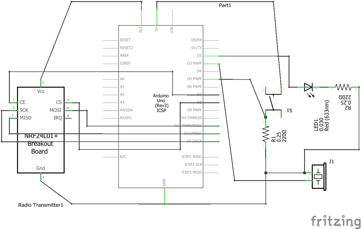
The schematic of the receiver is fairly simpler compared to the server since all it has to do is to notify the caregivers when the data of the heartbeat or the level of oxygen of the patient exceed the margin of acceptance. According to the diagram, the receiver contains one LED and one Buzzer. These two output devices are there to make sure that the caregivers will be notified visually and audibly when things when wrong.
The pushbutton is designed to turn off the output devices after the caregivers have already been notified and handled the situation. And again, there will be another NRF24L01 Wi-Fi module here in the receiver to receive the data sent by the transmitter. We decided to use the UNO processor for the receiver as we are only using one LED and one Buzzer. Also, the UNO processor is much cheaper than the MEGA processor, which met one of our important criteria of the project: affordability.