| layout | title |
|---|---|
documentation |
DSB54 - ZWave |
{% include base.html %}
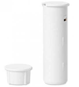
This describes the Z-Wave device DSB54, manufactured by AEON Labs with the thing type UID of aeon_dsb54_00_000.
The device is in the category of Door, defining Door sensors.
The DSB54 supports routing. This allows the device to communicate using other routing enabled devices as intermediate routers. This device is unable to participate in the routing of data from other devices.
The DSB54 does not permanently listen for messages sent from the controller - it will periodically wake up automatically to check if the controller has messages to send, but will sleep most of the time to conserve battery life. Refer to the Wakeup Information section below for further information.
Aeotec Recessed Door Sensor Gen5 has been crafted to power connected lighting using Z-Wave Plus.
- Place your gateway or controller into Z-Wave pair or inclusion mode.
- Press the Action Button on your Sensor.
- If your Sensor has been successfully linked to your network, its LED will become solid for 2 seconds then disappear. If linking was unsuccessful, the LED will continue to blink if you tap its button.
- Place your gateway or controller into Z-Wave unpair or exclusion mode
- Press the Action Button on your Sensor.
- If your switch has been successfully unlinked to your network, its LED will begin to blink for a short time. If linking was unsuccessful, the LED will return to its last state. Tap the button to confirm if it has been unpaired, if unpaired successfully, the LED will blink when tapped.
The DSB54 does not permanently listen for messages sent from the controller - it will periodically wake up automatically to check if the controller has messages to send, but will sleep most of the time to conserve battery life. The wakeup period can be configured in the user interface - it is advisable not to make this too short as it will impact battery life - a reasonable compromise is 1 hour.
The wakeup period does not impact the devices ability to report events or sensor data. The device can be manually woken with a button press on the device as described below - note that triggering a device to send an event is not the same as a wakeup notification, and this will not allow the controller to communicate with the device.
Press and hold the Z-Wave button for 6 seconds
Reset:
At some stage, you may wish to reset all of your Recessed Door Sensor's settings to their factory defaults.
- To do this, press and hold the Action Button for 20 seconds and then release it. Your sensor will now be reset to its original settings
The following table summarises the channels available for the DSB54 -:
| Channel Name | Channel ID | Channel Type | Category | Item Type |
|---|---|---|---|---|
| Door Sensor | sensor_door | sensor_door | Door | Contact |
| Battery Level | battery-level | system.battery_level | Battery | Number |
Indicates if the door/window is open or closed.
The sensor_door channel is of type sensor_door and supports the Contact item and is in the Door category. This is a read only channel so will only be updated following state changes from the device.
The following state translation is provided for this channel to the Contact item type -:
| Value | Label |
|---|---|
| OPEN | Open |
| CLOSED | Closed |
Represents the battery level as a percentage (0-100%). Bindings for things supporting battery level in a different format (e.g. 4 levels) should convert to a percentage to provide a consistent battery level reading.
The system.battery-level channel is of type system.battery-level and supports the Number item and is in the Battery category.
This channel provides the battery level as a percentage and also reflects the low battery warning state. If the battery state is in low battery warning state, this will read 0%.
The following table provides a summary of the 7 configuration parameters available in the DSB54. Detailed information on each parameter can be found in the sections below.
| Param | Name | Description |
|---|---|---|
| 1 | Send Sensor binary report on open/close events | |
| 3 | Send Basic Set on open/close event | |
| 101 | Low battery voltage check | Enable battery check |
| 111 | Low battery voltage check time | Minimum battery low check Interval time is 4 minutes (240 seconds) |
| 121 | Flag values for triggered magnet switch | Flag values for which reports to send when the magnet switch is triggered |
| 252 | Permit other configurations | Lock or Unlock other configuration set function |
| 255 | Reset to default | Reset to the default configuration |
| Wakeup Interval | Sets the interval at which the device will accept commands from the controller | |
| Wakeup Node | Sets the node ID of the device to receive the wakeup notifications |
The following option values may be configured -:
| Value | Description |
|---|---|
| 0 | On for opened, Off for closed |
| 1 | Off for opened, On for closed |
The manufacturer defined default value is 0 (On for opened, Off for closed).
This parameter has the configuration ID config_1_1 and is of type INTEGER.
The following option values may be configured -:
| Value | Description |
|---|---|
| 0 | On for opened, Off for closed |
| 1 | Off for opened, On for closed |
The manufacturer defined default value is 0 (On for opened, Off for closed).
This parameter has the configuration ID config_3_1 and is of type INTEGER.
Enable battery check
The following option values may be configured -:
| Value | Description |
|---|---|
| 0 | Disable |
| 1 | Enable |
The manufacturer defined default value is 0 (Disable).
This parameter has the configuration ID config_101_1 and is of type INTEGER.
Minimum battery low check Interval time is 4 minutes (240 seconds)
Values in the range 0 to 65535 may be set.
The manufacturer defined default value is 112.
This parameter has the configuration ID config_111_4 and is of type INTEGER.
Flag values for which reports to send when the magnet switch is triggered
Values in the range 0 to 65535 may be set.
The manufacturer defined default value is 256.
This parameter has the configuration ID config_121_4 and is of type INTEGER.
Lock or Unlock other configuration set function
The following option values may be configured -:
| Value | Description |
|---|---|
| 0 | Unlock |
| 1 | Lock |
The manufacturer defined default value is 0 (Unlock).
This parameter has the configuration ID config_252_1 and is of type INTEGER.
Reset to the default configuration
1, Value=0x55555555、Default=1、Size=4
2, Value=0、Default=1、Size=1 Reset all configuration
parameters (except the parameter 254) to default settings.
3, Other values will be reserved.
Values in the range 0 to 65535 may be set.
The manufacturer defined default value is 0.
This parameter has the configuration ID config_255_2_wo and is of type INTEGER.
This is a write only parameter.
The wakeup interval sets the period at which the device will listen for messages from the controller. This is required for battery devices that sleep most of the time in order to conserve battery life. The device will wake up at this interval and send a message to the controller to tell it that it can accept messages - after a few seconds, it will go back to sleep if there is no further communications.
This setting is defined in seconds. It is advisable not to set this interval too short or it could impact battery life. A period of 1 hour (3600 seconds) is suitable in most instances.
Note that this setting does not affect the devices ability to send sensor data, or notification events.
This parameter has the configuration ID wakeup_interval and is of type INTEGER.
When sleeping devices wake up, they send a notification to a listening device. Normally, this device is the network controller, and normally the controller will set this automatically to its own address. In the event that the network contains multiple controllers, it may be necessary to configure this to a node that is not the main controller. This is an advanced setting and should not be changed without a full understanding of the impact.
This parameter has the configuration ID wakeup_node and is of type INTEGER.
Association groups allow the device to send unsolicited reports to the controller, or other devices in the network. Using association groups can allow you to eliminate polling, providing instant feedback of a device state change without unnecessary network traffic.
The DSB54 supports 2 association groups.
Association group 1 supports 5 nodes.
Association group 2 supports 5 nodes.
| Command Class | Comment |
|---|---|
| COMMAND_CLASS_NO_OPERATION_V1 | |
| COMMAND_CLASS_BASIC_V1 | |
| COMMAND_CLASS_SENSOR_BINARY_V1 | Linked to BASIC |
| COMMAND_CLASS_CONFIGURATION_V1 | |
| COMMAND_CLASS_MANUFACTURER_SPECIFIC_V1 | |
| COMMAND_CLASS_BATTERY_V1 | |
| COMMAND_CLASS_WAKE_UP_V2 | |
| COMMAND_CLASS_ASSOCIATION_V1 | |
| COMMAND_CLASS_VERSION_V1 |
Did you spot an error in the above definition or want to improve the content? You can contribute to the database here.