- STM32 - Prototypes Received. STM32F072 MCU, board is being tested.
- SK6812MiniE - Nearing final release.
- Bluetooth - In Progress. Initial design for the PCB is ongoing, need to research more on the MCU and batteries.
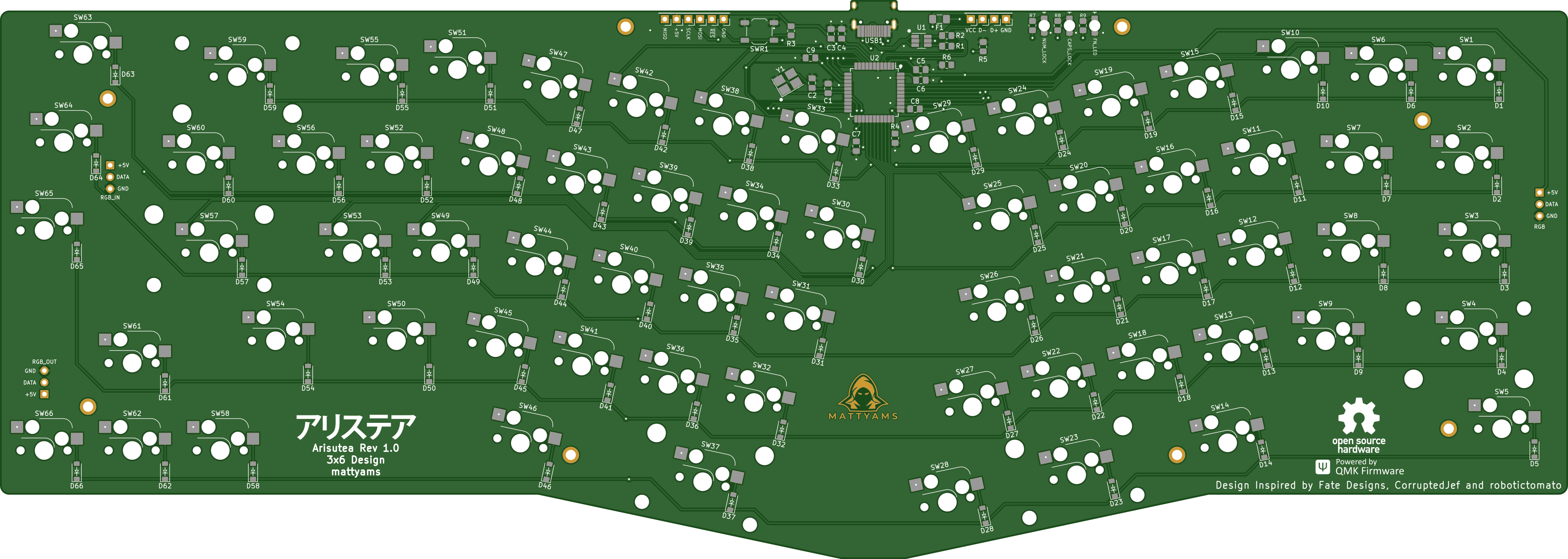
アリステア PCB designed using KiCad. The layout was originally created by FateNozomi, inspired by Lyn's EM7 and TGR Alice with some modification. The layout was then modified by CorruptedJef and robotictomato to add USB-C, ESD and to shift/add some keys. This inspired me to modify the layout further by adding the ability to swap your switches out whenever you want and to make some keys a little more permenant. I have designed many boards in the past but never a keyboard so this is my first crack at it and I figured why not go all out? If you notice any issue please open an issue and we can discuss!
Since the layout has been modified yet again I decided to give the project a new name, Arisutea, which translates to Alistair. Obviously keeping the theme running here.
Check out the iBOM here! This was generated with InteractiveHtmlBom!
Key modifications to the PCB:
- Added in Kailh Hotswap sockets.
- Addition of full backspace position, connected to switch 59 (row 0, column 13).
- Removed switch 63 and repositioned switch 59 to add full backspace position.
- USB-C ESD rework.
- Added underglow LED strip support (v0.6+)
- Added LED indicators for CAPS and NUM lock as well as layer. (v0.6+)
- Updated JSON layout file for this particular keyboard.
- Original mounting holes have been returned to their rightful place. The idea of widening them was good at the time for FR4 plates, but not very practical. A redesign is ongoing of the case to allow for brass inserts and standoffs to be installed so the PCB will be nice and snug. More on that later. FR4 plates still will work but you will have to drill the holes out manually. If you take this route....go forth cautiously adventurer.
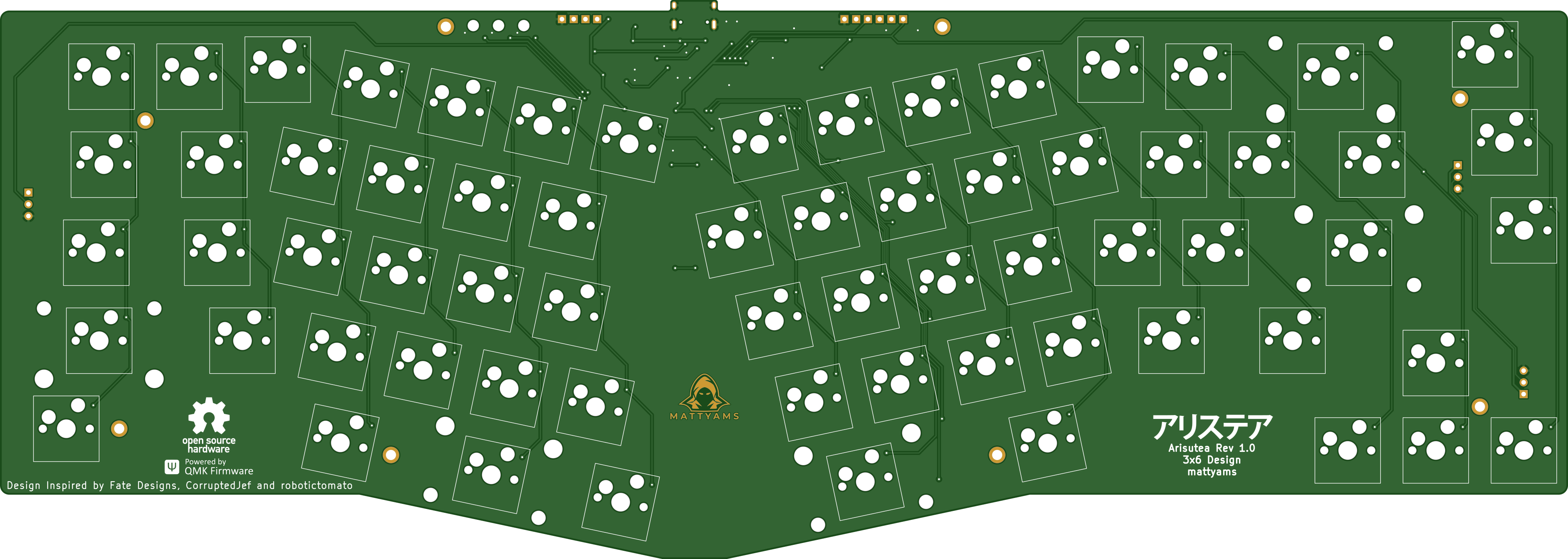
Renders generated by Tracespace.


Messing around with different switches.
This can be located in the firmware folder.
Case files are updated to reflect changes to the full backspace on switch 59 and can be found at its repository arisutea-case. The most recent case rework works very well with the changes made to the full backspace and addition of the stablizer on the prototypes designed by CorruptedJef and robotictomato. There is now a "boxed" version of the case that is designed to work with some wrist rests that do not have the ortho shape AND case files for version 0.6+ PCBs that include the indicator LEDs.
Additionaly, there are files for FR4 plates to be made and used with this layout. These can be found at its repository FR4_Plates. The plates are designed to fit with the full backspace and non-stepped capslock. That being said, these will not work on the original Fate Designs PCB. No plans to create plates for the LED indicators on the v0.6+ PCBs. NOTE FOR v0.6.3+ PCBs & RGB! FR4 plates still will work but you will have to drill the holes out manually. If you take this route....go forth cautiously adventurer.
Key differences:
- Removed the extra [B] key on the right half and shifted the [NM,.?] row to the left by 0.25U.
- Shifted the 3 keys to the right and added arrow keys.
- Tweaked the bottom so that the 1.5U keys doesn't protrude out a little.
Shifting the [NM,.?] row to the left by 0.25U required quite some work on the arrangement of keys for the right half. As a result, this does not give the same typing experience as Lyn's EM7 and TGR Alice. Lyn's EM7 and TGR Alice uses the home row as the center point to vertically align both halves while I used the number row instead. Due to the nature of staggered keyboards, aligning using the number row resulted in the home row not being aligned.
Disclaimer: Use these files at your own risk.
Download the gerber files under releases.
SMT/SMD position files are no longer included for any fab house. There have been too many issues with positions wrong, missing parts, etc.
For the components required, you may refer to the bill of materials included along with the release as reference or load up the design file in KiCad. All the components can be soldered using a regular soldering iron, though soldering the USB-C receptacle might be the biggest hurdle. Adjustments have been made to the USB footprint to allow for a little more error when handsoldering. Take care when soldering the LEDs to the board, too much heat can destroy the chip.


