[FEATURE] Chinese Translation #88
Comments
|
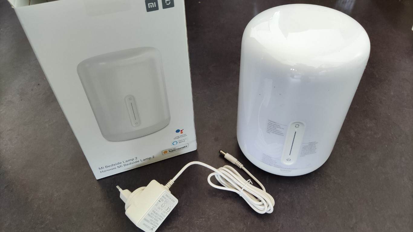
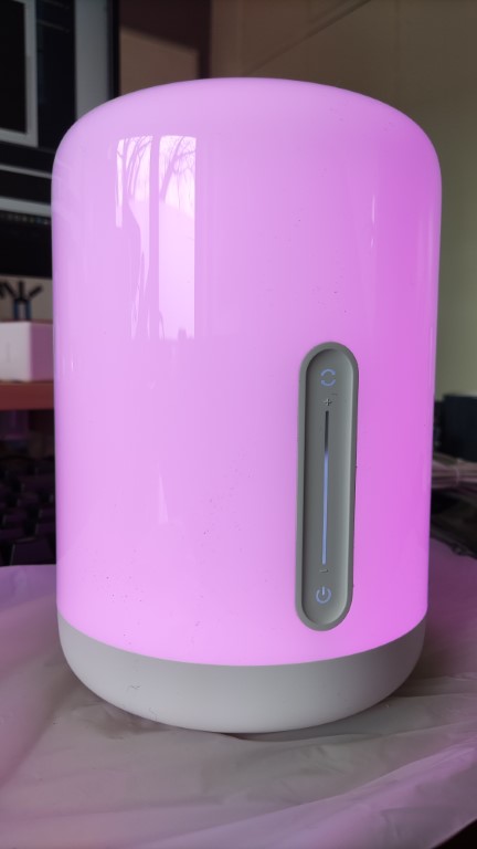
README.zh.md 对小米®米家床头灯 2 进行 ESPHome 兼容支持小米®米家床头灯2是一款智能型三色二温(EGBWW) 的 LED 照明灯具,由易来(Yeelight)公司替小米®米家品牌代工。这款灯具可以通过Wi-Fi网络以及该机器前侧的触摸面板来对其进行操控。触摸面板带有电源键、变色键还有一个控制灯光亮度的滑条。 本项目为用户提供客制化后的 ESPHome 组件,使得用户对本照明灯具进行全方位的完全控制,并把本照明灯具加入到您的家居助手(Home Assistant)里成为可能。 功能
快速开始指导对刷ESPHome到机器中有经验的人可以来看看:
升级我总想让这个机器不用进行其他修改就可以升级固件。但有些时候,根本不可能完成。如果升级失败,升级的说明在这里。 内容一览表 |
|
Xiaomi and Yeelight annoying you is not good :-) Are you translating all of the project, or mainly the starting page? |
I'll translate the whole project, but it will take time, which I am not have quiet amount of that precious. And I have to do some updates from time to time here and there. I promise that will not use machine to translate it. But I am also unexperienced. So please bear with me till I get it all done. I will translate in a sequence that I think is proper. The Format Being Like: File path |
|
doc\flashing.zh.md 刷机指导目录:
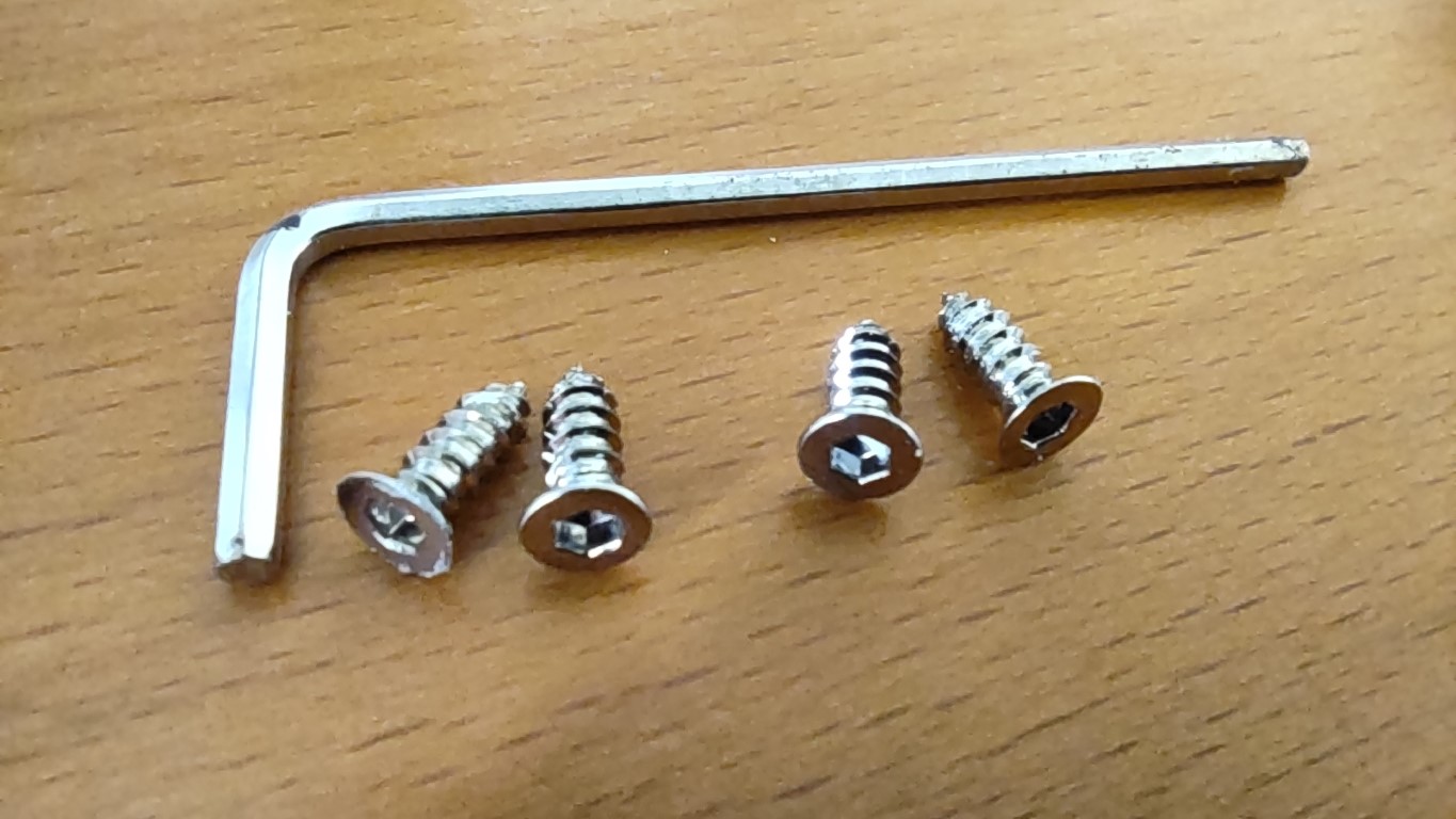
警告这里的指导都是我们用心撰写的, 不过我们不能给予读者任何保证。也许在操作途中读者会弄坏读者自己的照明灯具和读者自己的电脑。 所需工具
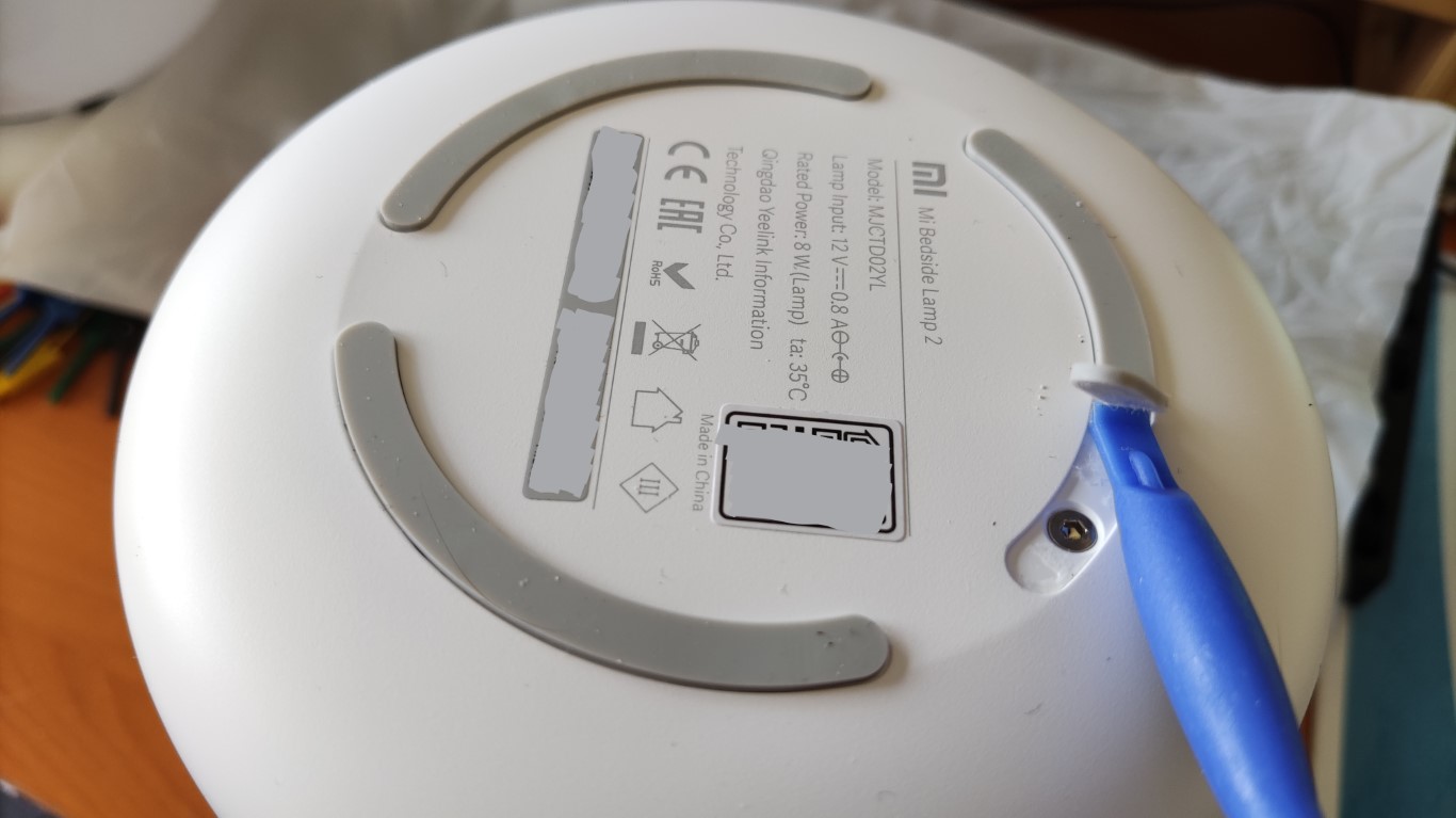
拆灯, 露出印刷线路板提示: 读者可以任意点击下方图片以查看完整尺寸图像。 移除照明灯具底部的胶垫, 可以看到照明灯具底部的连接灯具主体的 4 个螺丝孔。
注意并不需要把胶垫全部剥离。只要能看到螺丝孔, 一般就够了。
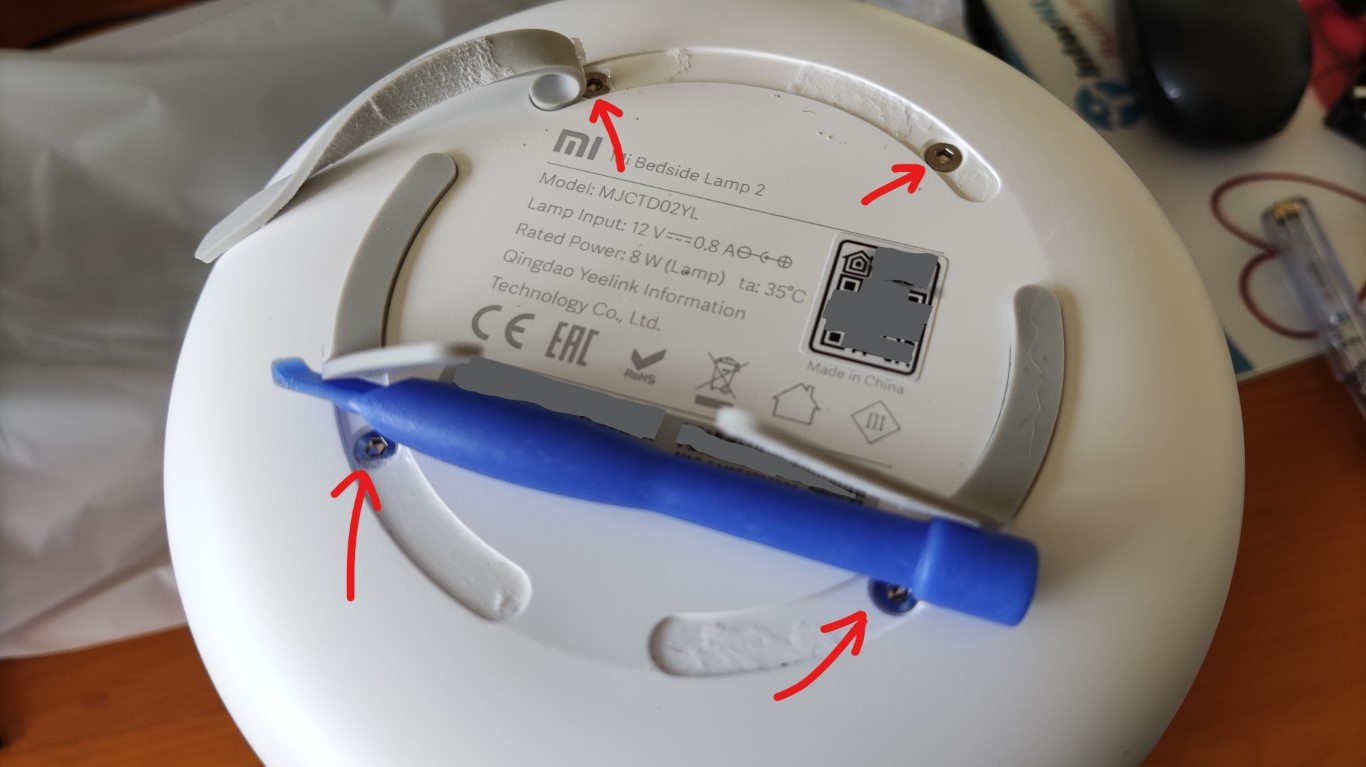
把胶垫隐藏起来的4个螺丝卸下来。
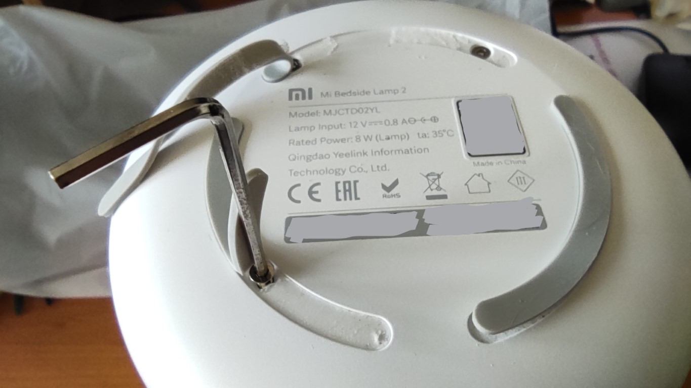
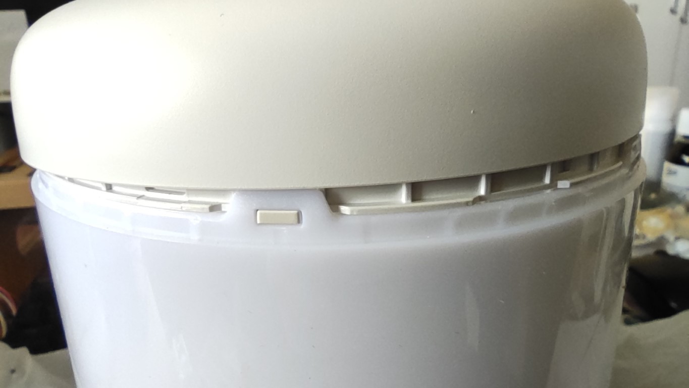
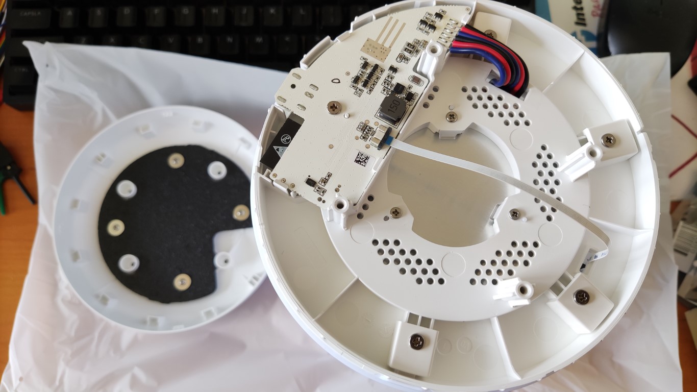
把照明灯具底部和灯具的其他部分拆开, 露出印刷线路板。可能得稍微用点力才行。一点一点的把底座拉下来, 一直到底部脱落为止。
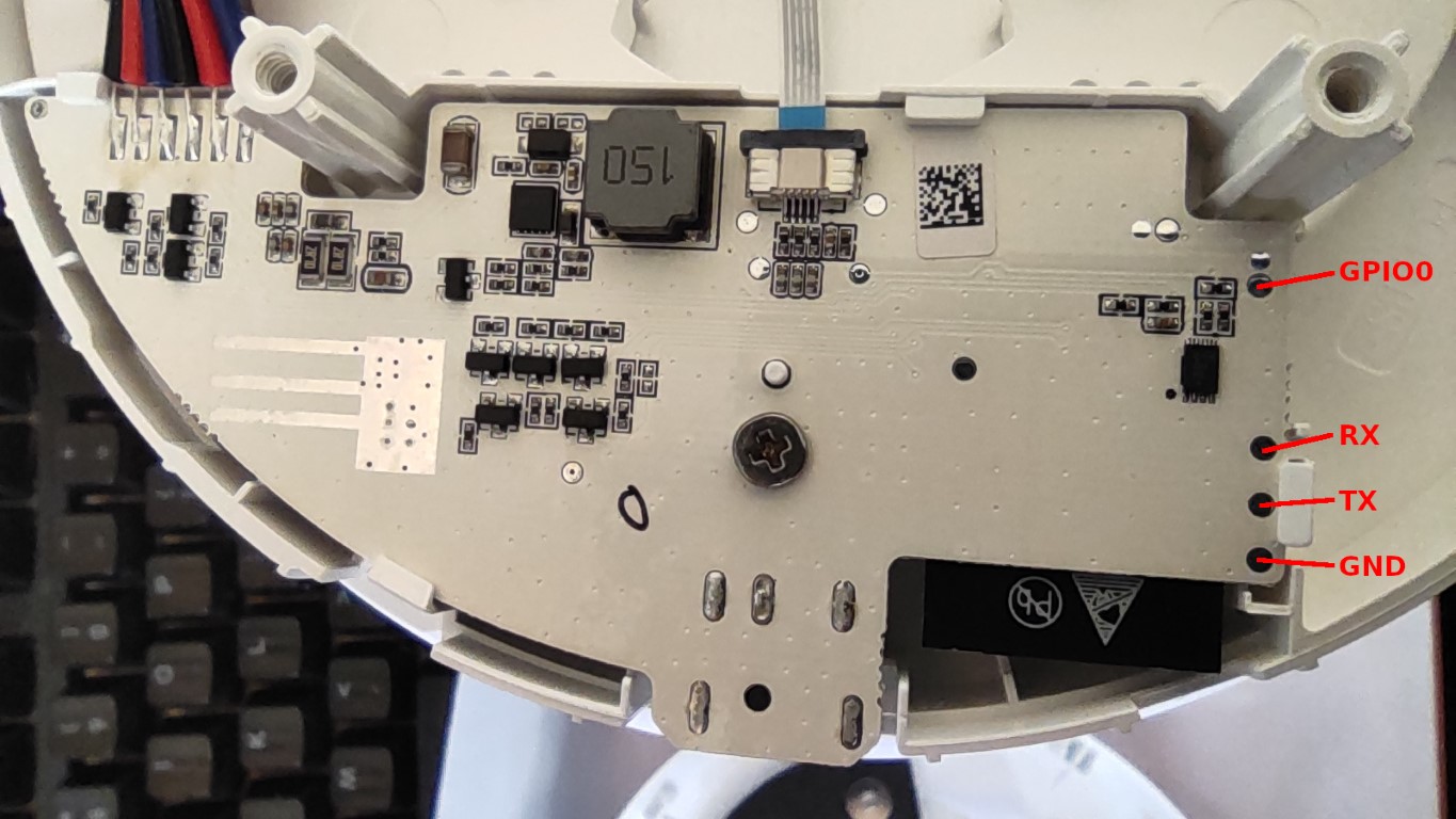
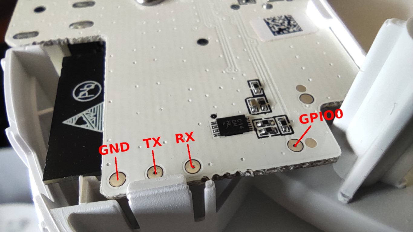
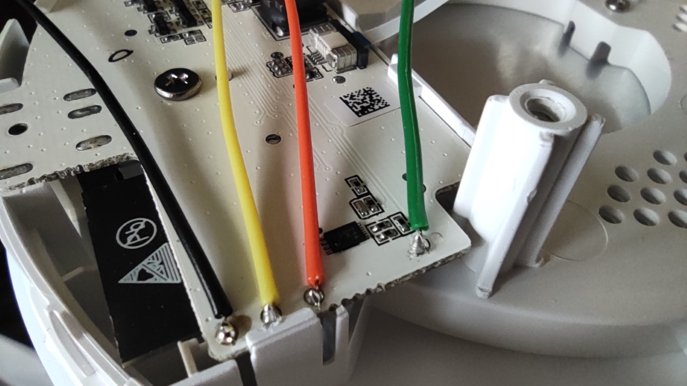
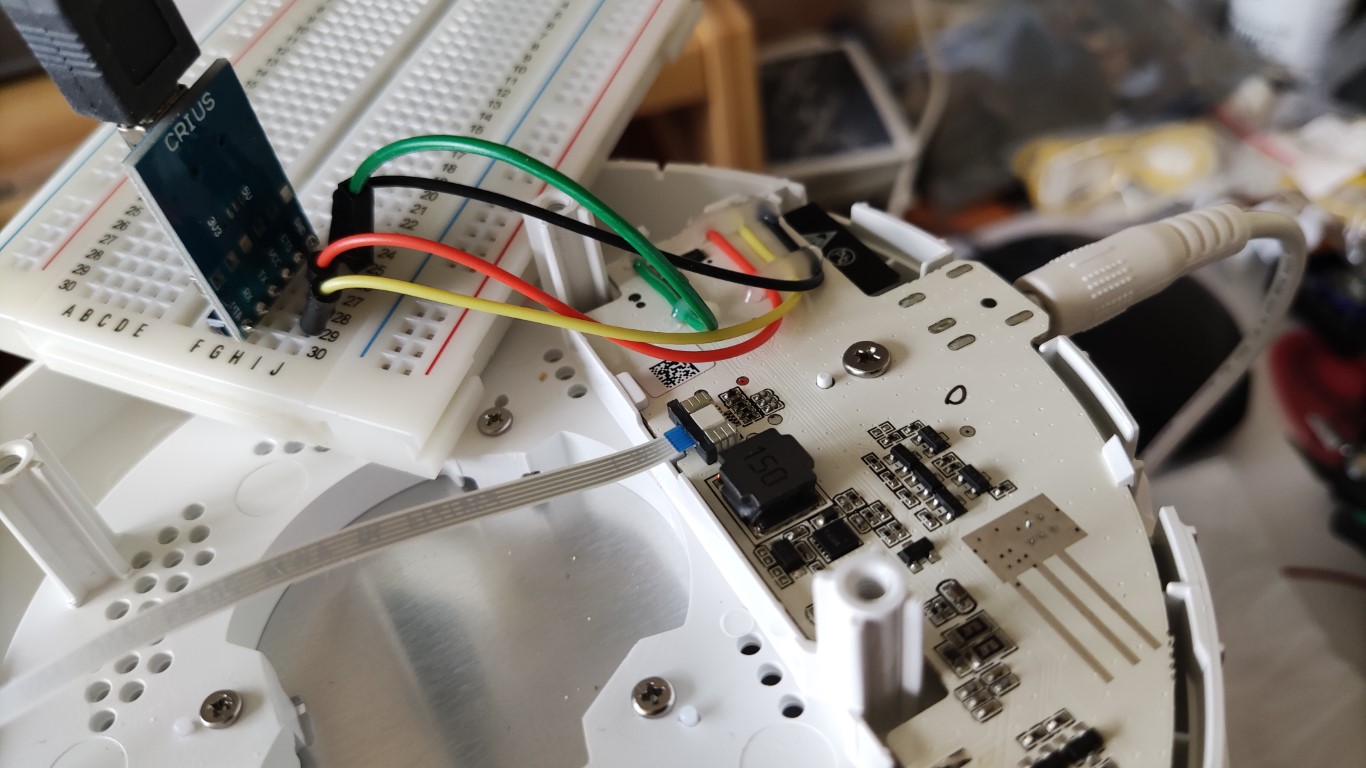
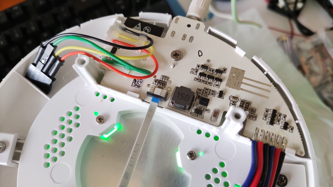
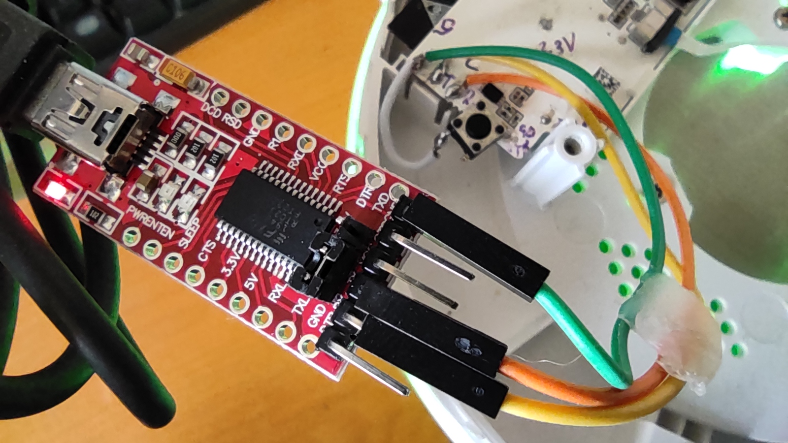
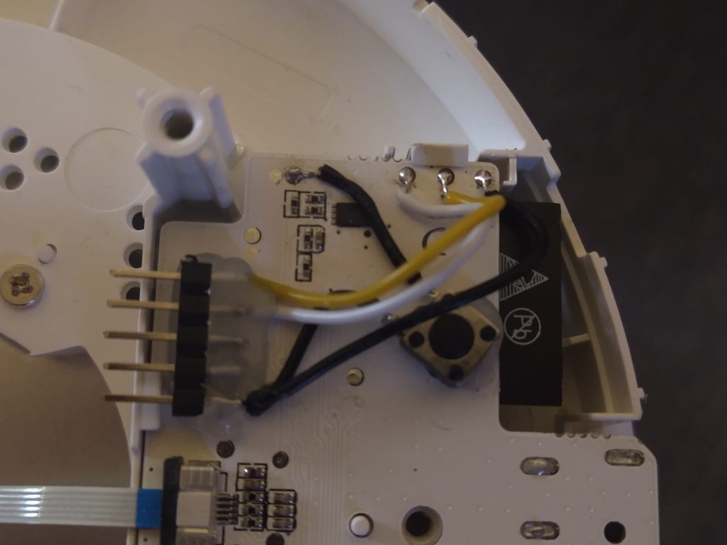
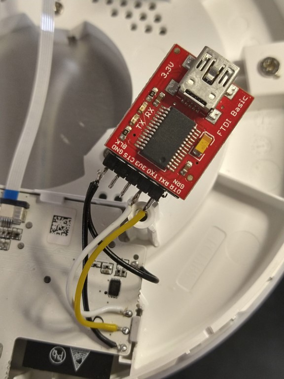
把转接线焊到灯具主板应该把转接线连接到调试接触点, 如下图所示。
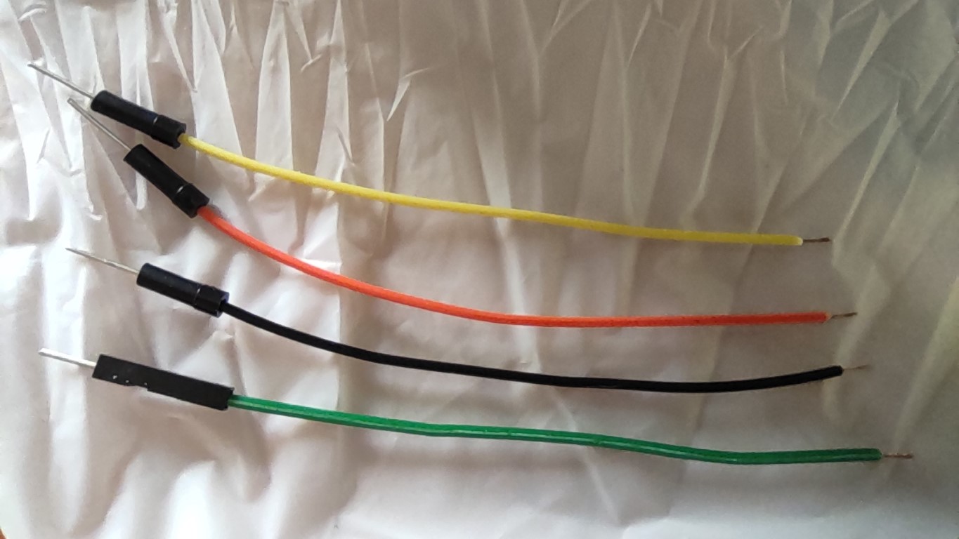
许多串行转USB适配器有一些 引脚头(Header Pin), 让读者可以把转接线接到设备上(并不需要焊接操作)。于是乎, 使用 杜邦线(Dupont Wire) 可能更加实用一点。把转接线尾部掐折、拨线、上焊锡、把转接线接到灯具主板上。 注意: 到底是使用插入式还是被插式线头这点取决于读者想怎么接在串行适配器上。在本范例中, 作者我本人使用的是插入式转接线, 这样我直接能把转接线插入适配器板上。
焊接转接线到 注意: 经过测量本灯具的主板上有一个调试接点提供 3.3V 电压 。一定不要企图采用串行适配器的接头连接本调试接点, 妄想借此给主板供电。要时刻确保照明灯具的电是从灯具自己的电源供应来供电的。 一些提示:
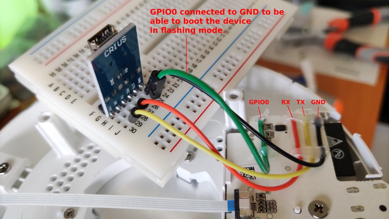
连接转接线到读者的串行转 USB 适配器确保读者要连接到照明灯具的适配器的 收发(RX/TX)针 采用的是 3.3V 电压。有些适配器或许会提供 3.3V 与 5V 切换的功能, 一般要么是有开关, 要么就是有跨接器。不要选用只能输出 5V 的适配器。原因是因为, ESP32芯片的工作电压是 3.3V, 我亲测该芯片也是可以接受5V电压的(也刷机成功了), 但是我并不确定该芯片可以忍受 5V 的电压。因此, 没有什么必要, 别做傻事! 转接线必须以以下方式进行连接:
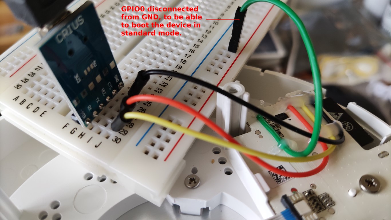
为了刷灯, 开机的时候 读者的 USB 适配器只有一个 GND 针怎么办要是读者的USB适配器没有多个
下列图片的内容, 是第一种的解决办法, 使用面包板的那个办法。
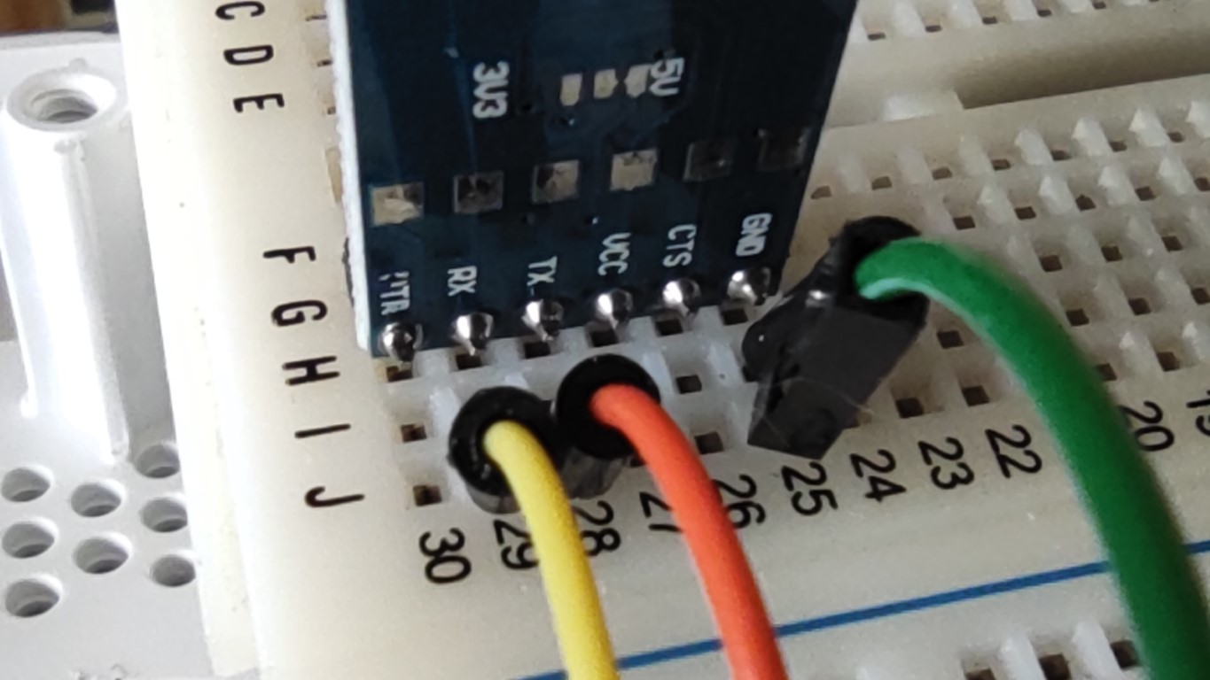
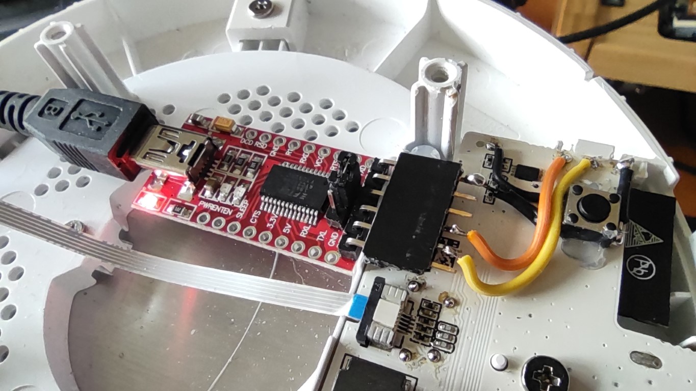
近景:
现在读者可以将串行转USB适配器连接到您的电脑上了。要特别注意 收发(TX/RX) 转接线的两端需要进行**交叉接线** 的常识要则 (主板上写 发送( 好了, 可以插入灯具的电源供应开机了。
由于
对现有固件进行备份对现有固件进行备份, 在读者使用 ESPHome 固件的期间有问题的话就有办法刷回官方原版固件。备份可以通过ESP工具包("esptool")制作。安装流程可以在这边找到: https://github.com/espressif/esptool/blob/master/README.md#installation--dependencies 以下是利用Linux系统备份原始固件的范例。首先, 拔掉灯具的电源供应, 然后开始 ESP工具包(esptool) 读取刷机(read_flash) 命令:
Now plug back in the power supply. The output of esptool should now show that it connects to the Caution: You will find the WLAN SSID and Password of the last used WiFi network in this file. How to restore the backed up firmwareIn case you need to rollback to the lamp's original firmware at some point, here's an example of how First, unplug your lamp's power supply, then start the esptool write_flash command: Make sure that Be patient after the upload reaches 100%. The output is silent while esptool tool is verifying that After the firmware upload completes, unplug the power, disconnect Flash new ESPHome firmwareSetup an ESPHome Project (see README.md), compile the firmware for the lamp and You can flash the lamp using esphome or esptool. I would strongly recommend using the
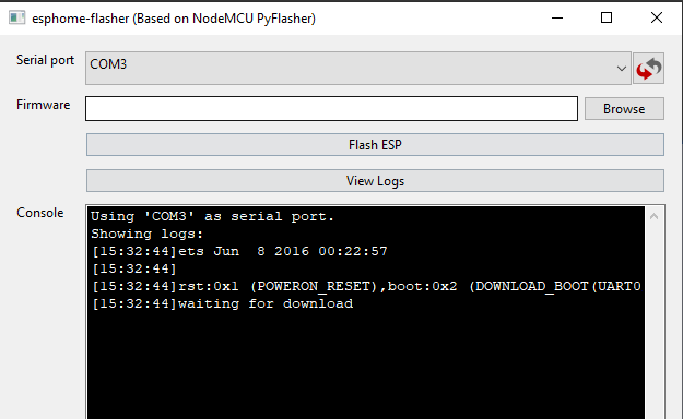
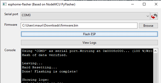
If all went well, the final log output in esphome-flasher looks somewhat like this:
If you want to flash with esptool, you can use the following command. Note: unless you know exactly what you're doing with esptool here, I recommend to use the The required .bin files can be found in the following locations:
After flashing, power down the lamp, disconnect
The lamp should now be operational using the new firmware.
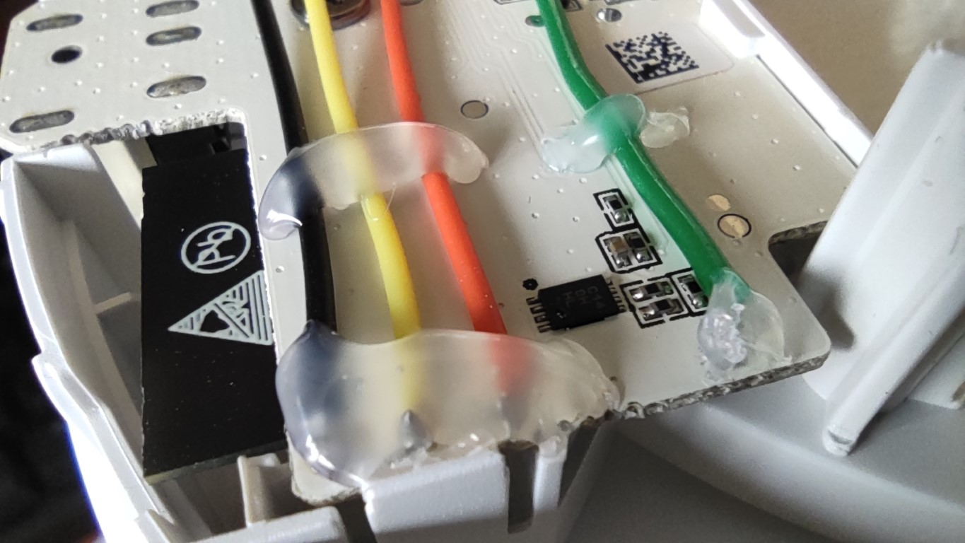
From here on, it is possible to flash the lamp OTA (over the air, which means that the firmware is Because I want to keep them around for future use, I tuck them away, making sure that the connectors
The bottom cover can now be put back on. The lamp is ready for use.
Troubleshooting flashIf you have A fatal error occurred: MD5 of file does not match data in flash!, then make sure After seeing this error, user @tabacha was able to successfully flash his lamp using the regular |
|
I thinks it's easier to get it done through pull requests. Copying and pasting from here might end up in errors.
"edit this file". After editing, you can do "Propose changes" at the bottom, to send in a pull request, which I can then accept. I added some files to the project tree, so you can work with those: I updated the internal links, so the README.chinese.md links point to the files inside the doc.chinese/ folder and the images are used from the English doc/images/ folder. I already copied over the translated text from README.md to README.chinese.md. |

Translation provided by: @Thisisnotgoingpublished
See: #88
|
Thanks~ I just realized that you wont be online for a long time, and if you ever come back, you can just pick the latest pull. |
Is your feature request related to a problem? Please describe.
I want to translate this project. I find Xiaomi and Yeelight is annoying me. It's been almost a year since i contacted to both Xiaomi and Yeelight. And about one month since i complained to 12315, yet no one want to solve this.
Describe the solution you'd like
Me by offering the translation.
Describe alternatives you've considered
Google Translate
The text was updated successfully, but these errors were encountered: