                                       ++++++++++++++++++
                                  +++++++++++++++++++++++++++++
                              +++++++                      +++++++++
                          +++++++                               +++++++++++++
         ++++++++++++++++++++                                         ++++++++++
    +++++++++++++++++++++                                                     +++
   +++++                                                                       +++
  +++         ######### ######### ########  #########  #########   +++++++      ++
  +++  +++++ ####  #### ######## ####  #### ##### #### #### ####  +++  ++++    +++
  +++   ++++ ###     ## ###      ###    ### ###    ### ###    ### ++++++++   +++
   ++++ ++++ ########## ###      ########## ###    ### ###    ### ++++    +++++
    +++++++   ###### ## ###       ########  ###     ## ##     ###  ++++++++++
The Garonne project is a simple infrastructure for autonomous and ADAS model vehicles. It has been run on numerous embedded and application platforms. The system consists of a Low Level Board (LLB) which is a real time embedded plaform (optionally multi-core) and a High Level Board (HLB) which performs the 'reasoning' behind the actions the system takes. Many different platforms have been used for the HLB and the LLB including Tegra TK1 and full blown PCs.
Its designed to be cheap to build, modify and crash....but to be a reasonably powerful and extensible platform at the same time.
In the current implementation, for ease of access, the High Level Board is minimally a Raspberry Pi and the Low Level Board is a NXP LPCXpresso LPC4367 204MHz CORTEX-M4 + 2x CORTEX M0 which provides a significant amount of real time computing power. The HLB runs Linux, programmed in Python, and the LLB is based on FreeRTOS and is programmed in C. The Commander (that animates the system and provides objectives to be reached) can run on pretty much anything, but the simple code provided will work perfectly well on a second RaspberryPi....you can even use Force Feedback wheels etc. for 'driving' the vehicle remotely.
The project was orignally created by Technolution BV. It was first demonstrated at the ITS World Congress in Bordeaux in 2016 (Hence, the codename 'Garonne', the river that Bordeaux lies on) based on bespoke hardware. It has been ported to COTS hardware by Technolution and is now released for open use.
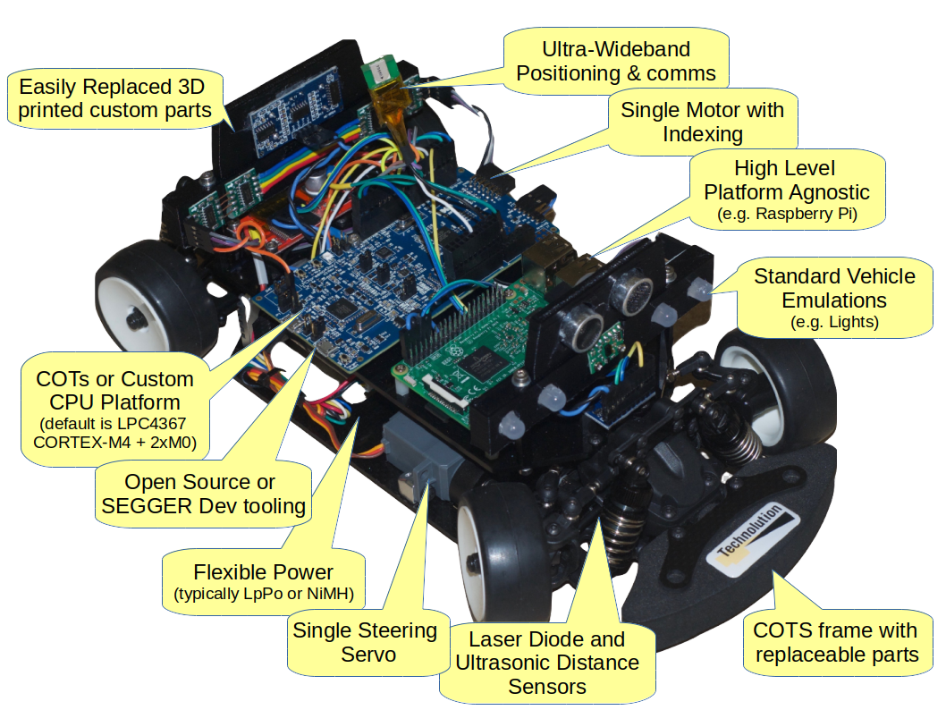
Generally speaking, a Garonne system will consist of at least one vehicle, a control platform (consisting of a Low Level Board (LLB) and a High Level Board (HLB) and a command platform, which is generally remote. All of this runs on a physical vehicle which ends up looking something like this;
...so, let's get started;
Generally speaking, you can use most remote controlled cars for the physical vehicle, the requirements are not very onerous.
The shopping list looks like the following (Full list of compnents and quantities is at the foot of this note);
-
M.Rage chassis, assembled. Hobbyking. The assembled bit is an exercise for the reader.
-
Steering Servo...just a bog standard analogue servo will be fine. Something like this.
-
Pololu motor, mounted in chassis, with drive pinion. We use the 4.4:1 variant which is expensive, but comes with itw own encoder and they're available from distributors around the world. [Pololu item number 2270] (https://www.pololu.com/product/2270).
-
Drive Pinion. The most specific bit of the whole setup. These are 31 tooth 48P pinions with 5mm bore. We get ours from neil at rwracing.co.uk. Take a guess at his email address.
-
Power Switch. You can use anything for this really, but the plastics have a 13x19.5 hole cut to take a snap-in switch. The ones we have are marked KCD1-104 and work fine. Available for cheap from the usual outlets.
-
Mounting plastic for the electronics. No way out of this one, you've got to make them, or talk very nicely to me to see if we've got any spare, we often have, but shipping outside of local territory tends to end up more expensive than making new ones. The drawings to make them from are in the git repository, and [Elecrow] (https://www.elecrow.com/) will make you more than you'll ever need in 3mm acrylic for very cheap.
-
LPC4367 LPCXpresso board. These are available from [Farnell] (http://uk.farnell.com/nxp/om13088/dev-board-32bit-dual-core-mcu/dp/2519578) and elsewhere. Again, not cheap, but you're getting a CORTEX-M4 and two CORTEX-M0 CPUs here, complete with development environment and debugger.
-
MPU9250 9D sensor board. Search for '9DOF MPU9250' or similar on eBay. It's just a chip on a board so it's difficult for them to screw it up too badly. Make sure you end up with a 9250 board and not a 65 series board though....they're largely identical but the one with MPU65 written on the top doesn't have the magnetometer built in.
-
Raspberry Pi 3...'nuff said. The plastics also support the little mini ones, and the PiW has wifi on now too. Which one you choose is dependent on how much processing you want to do on the vehicle. We've used all sorts for this job from a Pi to a TEGRA K1 and a Parallella. You can connect to the LLB via TTL-serial or USB, so there's flexibility here.
-
VHN2SP30 motor driver. Again, this is an eBay job. You only need the single one, not the dual that is set up as an Arduino shield.
-
5V power supply. There are 1001 of these. We use the little MP1584 modules set to 5V with a dab of nail varnish on the pot afterwards. Use whatever you prefer but beware there are many stories of fake modules coming out of China. They usually work fine but I wouldn't trust them anywhere near their stated current limits!
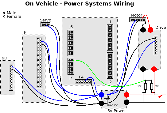
In addition to this lot you will need some male to female and female to female 10cm and 20cm Dupont jumpers, and some nylon m3 standoff pillars. In the Wiring directory you will find a set of wiring digrams for Power;
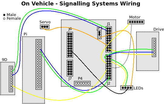
... and for signalling;
Higher resolution versions of these diagrams can be found in the Wiring directory in PDF format.
Bringing up the Low Level Board (LLB) requires the use of the GNU ARM gcc compiler suite. You can download that directly from [ARM] (https://developer.arm.com/open-source/gnu-toolchain/gnu-rm) and then use something like GNU ARM Eclipse to fold it into an IDE (http://gnuarmeclipse.github.io/) or, the easier option, is to head over to NXP and download either LPCXpresso or MPUXpresso from their site. MCUXpresso is the more recent suite, and is arguably more powerful, but it's a new product and at the time of writing we found LPCXpresso 8.2.2 to be more solid than MCUXpresso 10.0.0....but the letter is likely to be updated frequently, so YMMV. Having said that, as we've brought up the M0 cores, we've not found either of these suites to be great, so we've installed the Segger JLink firmware (available for download from the Segger Site ) and used it with the GNU Arm Eclipse setup. This makes for quite an impressively capable setup.
The code for the LLB is well commented and will build directly from the Makefile with a make command...or import it as a makefile project into one of the aforementioned environments. It will flash directly onto the LLB using the built in debugger. You've got to go a long way out of your way to brick this setup...indeed, I doubt you could do it without deliberately setting out to do so.
The LLB code is reasonably well structured, and there are lots of optional components that can be included via conditionals in the makefile (e.g. for networking, SD cards and CAN interfaces). The primary components to be interested in are;
config.h: The main configuation file, which pulls in a susbsidiary configuration fileconfig-lpc4367.horconfig-lpc4370.hwhich are the only two we have released. In each of these files you will find things like pin allocations for the various components and the configuration of I/O flows (e.g. which UART is used for the UI and which is used for HLB communication, for example). In general make changes in these files rather than the program files themselves where possible.
The code for the various CPUs lives in subdirectories. For now we only concern ourselves with the m4 code, which we split into several groups;
Program Flow Control
-
main.c: Sets up the system, calls essential configuration routines, and then gets out of the way having gotten everthing going. The main thread of execution is maintained in... -
mainloop.c: Runs two threads. One for the i2c tasks, and one for the primary tasks. These are seperated to avoid timing dependencies between the two. After initialisation the two threads inmainloop:_mainThreadandmainloop:i2cThreadrepresent the backbone of execution for the system. -
ui.c: The management and reporting UI. Not generally used in active operation, but very useful for debug and proving.
Offboard Communications
-
serport.c: Abstracted interface to all of the serial ports, both 'real' TTL ones and 'virtual' USB ones. -
lmsMsg.c,lms_rx.c&lms.c: The interface to/from the HLB. All messages are encoded and decoded here before being dispatched to the right places. -
uartHandler.c: Looks after the 'real' UARTs.
I/O
-
gio.c: The generic I/O module. Looks after the flashing lights, ADC and other low level stuff that is not worthy of its own module. -
leds.c: Code for driving LED strings (for indicators and headlights etc.).
Device Drivers and Real World Interfaces
-
rotenc.c: Provides a clever little routine to maintain the rotary encoder count from the motor. -
dist.c: Distance measuring via whatever transducers are in use. -
vldist.c: Distance module when using the ST VL transducer. -
motor.c: Motor (actuator) driving for both the direct drive motor and the Servo. -
can.c: Is a prototypical CAN interface. It was used for hardware proving and is not active in current builts. -
audio.c: Is a simple DMA based audio handler. Not wired in one the current board, but can trivially be added. The samples it plays out are stored inspeedy.c. -
sdif.c: Is the iterface to the SD Card that can be used for recording logging data etc. This was used in hardware proving and is not active in current builds. -
nined.c: Simple i2c interface to the 9D sensor. -
i2chandler.c: Generic i2c handler. -
usb/: Files relating to the USB interface. Most of the interface is implemented by ROMmed routines, but this code provides the interface to those. -
enet/: Files relating to the Ethernet interface. This is not active/needed at the moment (these files were used for hardware proving) but it's trivial to add by just provisioning a connector onto J6 of the LLB....previous versions of Garonne have used Ethernet for the interface between the LLB and the HLB
System Management
-
fault_handler.c: Provides support for debugging the bane of every ARM programmers life, HardFaults. -
config.c: Configuation support and Non-volatile storage. Asserts and debug printing are also handled in here. -
stats.c: Simple stats management package for FreeRTOS....it's really useful to know just how busy the CPU is! -
llb_init.c&startup_lpc43xx.c: Deal with the booting of the system.
There is code that runs on the M0 board for interfacing to the Ultrawideband radio and a Quaterion structure for the 9D sensor. I'm afraid we can't make the source code for these files openly availble but you're free to use the code with the Garonne platform (See the licence in the bindist directory, where the binary blob also lives). If you do need access to the source for this module then drop us a note and we will sort something out...but we've got to eat too!
The high level board is reponsible for the 'reasoning' that the on-board systems have to perform. It's also responsible for the interface to the outside world (over WiFi, in the implementation that is released). It's based on a RaspberryPi and a Pi3 or ZeroW both offer the WiFi on board.
The image on the board is based on Rasbian (downloadable from the Pi Foundation), then install Python3, the PySerial and evdev extensions, and you're ready to run the vehicleserver which is in the python directory of the distribution. You can edit the file /etc/rc.local and add the following lines to get the system to auto-start;
/sbin/iwconfig wlan0 power off
/home/icarus/runvs >> /home/icarus/vehicleserver.log 2>&1 &
If you do decide to to start vehicleserver from the command line then the -v option will provide you with some information as to what it is doing. In general, the vehicleserver won't do anything except the status quo until it receives a command from the outside world, which brings us to the highest level of the system;
The commander is the part of the system that tells the vehicle(s) what to do. In the released implementation you will find a wheelclient in the python directory of the distribution. This allows a number of different controllers to be used to control the vehicle directly. Currently supported controllers are;
- Logitech G29 Driving Force Racing Wheel (uses the force feedback - currently the best choice)
- Generic Steering Wheel Controller
- PLAYSTATION(R)3 Controller over Bluetooth
- Goodbetterbest Ltd Gioteck VX2 Wired Controller
- Microsoft X-Box 360 pad
When multiple controllers are connected to the Commander the selection amongst them will be performed in the order listed above. Adding new controllers is trivial via the code in wheelclient.
wheelclient will run on any Linux-style platform. For convinience it is often run on a second RasberryPi...indeed, if you're using a Bluetooth controller, it can even be run on the HLB.
wheelclient needs to be told where to 'find' the HLB on the network. A typical invocation of wheelclient would therefore be;
wheelclient -s icarus32n4.local
| Component | Per Vehicle |
|---|---|
| Frame | 1 |
| Plastic Motor Mount | 1 |
| Polulu 2270 motor | 1 |
| Servo Motor | 1 |
| 31 tooth 48P pinion with 5mm bore | 1 |
| Acrylic Baseplate | 1 |
| 10mm M2.5 Nylon Spacer | 4 |
| 10mm M3 Nylon Spacer | 9 |
| m3 nut | 9 |
| 30mm Nylon Hex Standoff | 4 |
| 6mm M3 Hex Head bolt | 13 |
| M3 Washer | 4 |
| 8mm M2.5 Cross Head Screw | 4 |
| 10x1 Dupont Housing | 1 |
| 10x2 Dupont Housing | 3 |
| 7x1 Dupont Housing | 1 |
| 6x2 Dupont Housing | 1 |
| 6x1 Dupont Housing | 1 |
| 20x2 Dupont Housing | 1 |
| 10cm 40 way Male to Female Dupont Jumper | 1 |
| 20cm 40 way Male to Female Dupont Jumper | 1 |
| 15cm 40 way Male to Female Dupont Jumper | 1 |
| Hookup wire for Battery (Black & Red) | 1 |
| Hookup wire for 5V Distribution (Black & Blue) | 1 |
| 56K 1/4 Watt Resistor | 1 |
| 10K 1/4 Watt Resistor | 1 |
| MPU9250 9D Sensor Board | 1 |
| Raspberry Pi 3 or PiW | 1 |
| 8GB uSD Card | 1 |
| Ultrasonic Transducer | 2 |
| LPC4367 LPCXpresso board | 1 |
| VHN2SP30 Motor Driver Board | 1 |
| MP1584 PSU (Adjust to 5V) | 1 |
| KCD1-104 Power Switch | 1 |
| DWM1000 Module | 1 |


