ESP8266 Wiring Questions #5256
Replies: 1 comment
-
|
Posted at 2016-01-15 by tve
Posted at 2016-01-15 by DrAzzy Oooh, is this for that board you mentioned a little while ago with a more-memory-heavy STM32 paired with an on-board ESP8266 for wifi connectivity? I'm definitely paying attention ;-) Posted at 2016-01-15 by tve Sorry if my earlier email was terse. My canonical esp8266 design has:
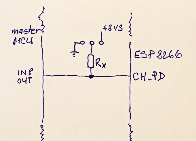
Posted at 2016-01-15 by profra If you are considering a new board with ESP8266 controlled by another MCU please take into consideration the serving of pin CH_PD by one output pin of the master MCU. In many situations we don't need to power on ESP8266 in the same time as master MCU (battery life), it means that on the PCB could be any jumper with two positions:
Posted at 2016-01-15 by @gfwilliams Thanks for all the info!
Yes, it's still very early days, but I'm working on a PCB now.
Yes, absolutely.
I doubt you really want this... When pulled down by the MCU it's using almost 1mA (3.3v / 4700 = 0.7mA) to fight against it :) @tve is there any reason for the resistor on GPIO15? I'm just trying to reduce component count :) Also, can CH_PD really act as reset? So I could just connect reset to 3.3v, and then use CH_PD with GPOI0 low to put the board into bootloader mode? It'd be nice to save an IO pin :) Switching regulator is a nice idea - any idea what the quiescent current of that one is? I'd like to keep the battery life as high as possible. P.S. I'm thinking of ditching the Battery + USB switchover FET. Just seems like extra trouble and I'm not sure anyone really uses it. Posted at 2016-01-15 by @MaBecker also check this ESP12 shifter from adafruit Posted at 2016-01-15 by tve ch_pd can indeed be used as reset. Posted at 2016-01-15 by profra
Surely the resistor can have higher value e.g. 10K but on the other side 0,7mA is 100 times less than avg. consumption of ESP8266 which is in ON state :)
... and still remains the possibility to generate RESET impulse and save one output of MCU for RESET signal Attachments: Posted at 2016-01-20 by DrAzzy Don't forget that some of the ESP modules have their own resistors on the module... For example, there seems to be a 4.7k pulldown on GPIO0 on the ESP12F modules I bought from the link @tve posted, unless I botched the soldering job something hardcore. That could make your board smaller (or at least cheaper). Posted at 2016-01-21 by @gfwilliams Thanks! I sent a prototype off earlier this week - I guess it's worth having pads for the resistors there, but if the modules I fit has then on then I can leave my boards's ones off. Posted at 2016-01-22 by DrAzzy Hm, I don't seem to need an external resistor on either GPIO0 or GPIO2 (using ESP12F modules) Posted at 2016-01-23 by tve At reset all the gpio pins have the internal pull-up enabled. However, given that that's pretty darn weak (40Kohm min) it may work sometimes and not other times. I do believe that the LED on the module is on gpio2, in that case the LED and it's associated resistor indeed act as external pull-up, though. Posted at 2016-01-23 by tve According to this reverse-engineered schematic, you can omit a pull-up on reset and on gpio2, but I would not skip the pull-up on gpio0... Posted at 2016-01-25 by @gfwilliams Thanks! That's really good to know... The prototype has been posted so I should get it back in a week or so - but by the look of it I'll skip the resistors (except for a pull-dowm on CH_PD), and will replace them with a LED on GPIO2. As I'll be connecting GPIO0 to the STM32, I can make sure it's set to the correct state. |
Beta Was this translation helpful? Give feedback.
-
Posted at 2016-01-14 by @gfwilliams
Hi, I'm looking at ways to connect an ESP8266 (ESP12) to an STM32 that leave maximum free pins available, and was wondering if anyone knew:
Beta Was this translation helpful? Give feedback.
All reactions