Power System Architecture
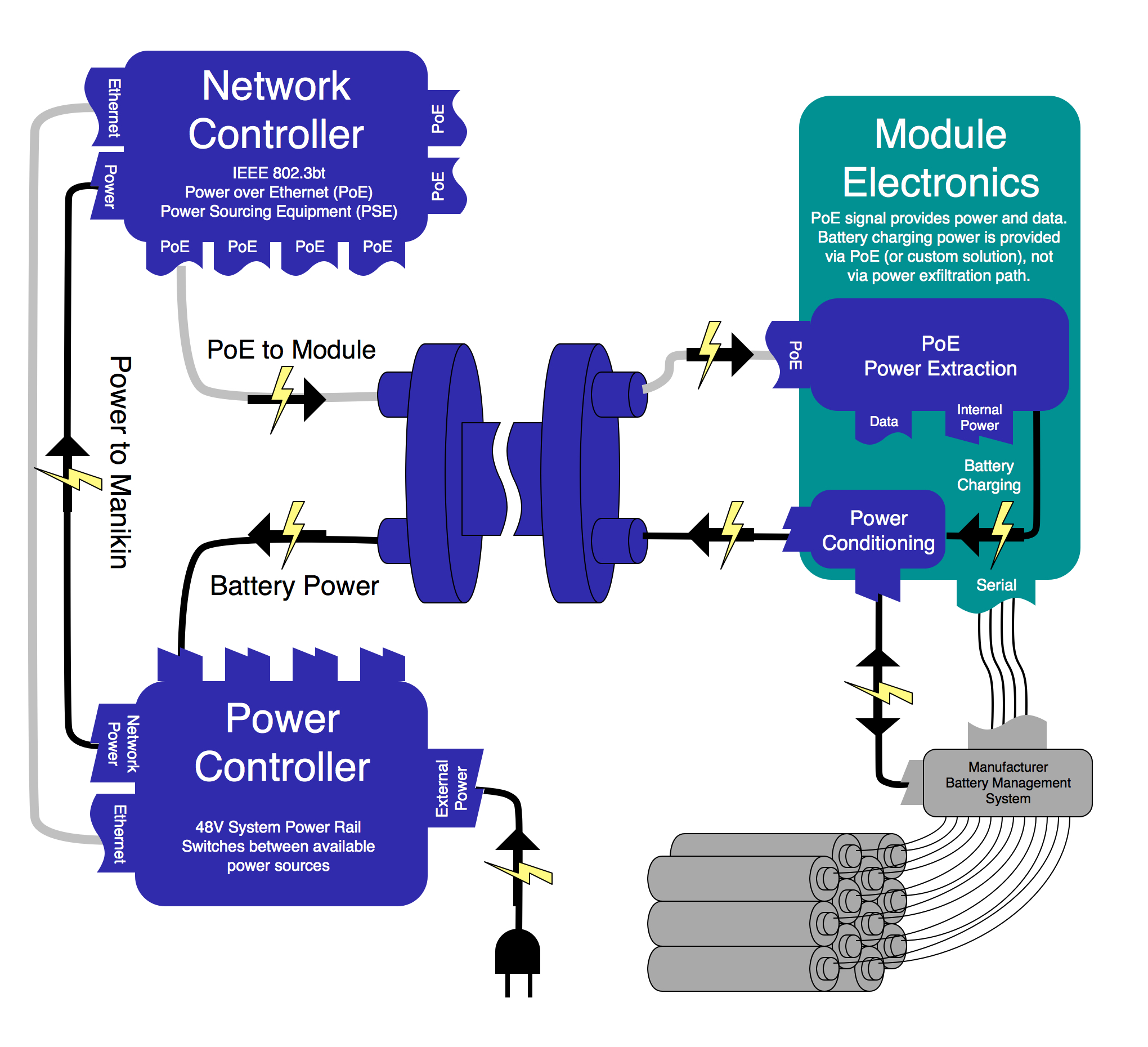
Hardware modules may receive power via the Power over Ethernet (draft) standard IEEE 802.3bt. Modules must monitor and their power consumption and report it via DDS (specifics still TBD).
Modules with batteries may provide power to a Power Controller via a dedicated high-power connection. The high-power connection is dedicated to battery power. Modules with batteries must subscribe and adhere to the power management DDS topics (specifics still TBD). Battery modules must also publish, via DDS, the status of their batteries, as reported by the Batter Management System (specifics still TBD).
Each battery pack will have a Battery Management System (BMS). The BMS will monitor the battery's status, including voltage, current, and temperature levels, along with capacity and charge cycles. The BMS will manage the discharge, charge and balancing of the individual battery cells. The BMS will prevent overcharge and over-discharge, and protect against over-currents and shorts. It will talk a standard protocol (probably SMBus) to the 'Tiny' MCU of the module, which will act as a relay between the BMS and the module control code.
The Power Controller will receive and condition input power, from either an external source or connected batteries, and provide power to the PoE PSE (power sourcing equipment).
The Power Controller will monitor the status of all connected batteries, control charging and discharging, monitor module power consumption, and alert manikin operator of any conflicts.
All intermediary segments (e.g. torso/abdomen) must contain a Power Controller to allow battery modules to supply power to other modules in the manikin.