- 2022 Top Prize, Creative Comprehensive Design Competition, Hanyang Univ. ERICA
- 2022 Gold Prize, International S.M.A.R.T Sustainable Technology Competition, Korea Sanhak Foundation
- 2022 Bronze Prize, Intelligent Robotics Industry Consortium Creative Comprehensive Design Competition, Hanyang Univ. ERICA
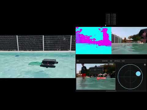
Positioning module for autonomous cleaning robots over the ocean
- 6DoF drift free pose estimation without loop closure using GPS
- Maintaining high stability using IMU bias divergence detection and divergence suppression loss function
- Acceleration of front and back end of SLAM using GPU
- Integration with navigation module using RGBD camera and occupancy grid OctoMap
6DoF drift free pose estimation using robot kinematics and GPS
The direction of robot displacement is usually the direction of the robot's heading, although there are effects from wind and water. When a series of GPS measurements are on a line, I want to force the direction of the line to be the estimated heading direction.
I first compute the covariance of the GPS sliding window elements. If the robot is stationary and the magnitude of the covariance, or the determinant, is below a certain value, I do not use this heading alignment process. This means that the heading correction must be linear in motion and at least a certain speed.
I perform a PCA based on the calculated covariance above a certain size. If the component in the major axis direction is significantly larger than the component in the minor axis direction, use the major axis direction as the heading direction.
Once the major axis direction is determined, I determine whether the collection of GPS measurements is negatively or positively oriented. I normalize the motion vectors between each element of the GPS window and add them together. I then compare the combined vector to the direction of the major axis (dot product). This allows for very robust direction estimation.
On the other hand, I define eigenratio as (major eigenvalue)/(minor eigenvalue). This is the relative stretch in the direction of the major axis. Find the variance of GPS heading based on the eigenratio. The assumed formula is

If the major and minor axes are the same size and eigenration is 1, the covariance is infinitely large. Conversely, eigenration greater than 1 has a smaller covariance, i.e., the covariance is smaller when the motion is large and linear. The above process has determined the covariance and direction, which are used in the heading alignment loss function.
Additionally, the robot only trusts these estimates when roll and pitch are small.
The altitude can be obtained from the GPS, but it is very inaccurate, so I ignore this measurement. Given the nature of our robot's motion in the ocean, I added a loss function that forces the altitude to be zero. This loss function has a large covariance to better reflect the short-term altitude changes in the visual inertial system while eliminating drift.
X, Y drift is eliminated by GPS.
Roll and pitch drifts are eliminated by the IMU.
Maintaining high stability using IMU bias divergence detection and divergence suppression loss function
The IMU measurement noise and bias variation, camera parameters, and IMU-camera synchronization were all carefully calibrated, but the IMU introduced a very large drift. This was the case even when using VI-Stereo-DSO, which led me to believe that the problem was largely with the IMU itself. The bias problem was especially noticeable with the accelerometer, which was bad for both velocity and position.
Since I couldn't change the IMU, I had to improve the optimization system to solve this problem. I believe that VINS fusion has insufficient bias constraints for poor IMUs. This is because only the covariance of the bias grows over time, and there is no constraint on the absolute size of the bias. ( Strictly speaking, the bias is constrained to be the same size as before.) This makes the bias sensitive to other states and measurements, and causes states to diverge out of the manifold.
To address this, I added a constraint on the IMU bias. To determine the mean of the bias magnitude, I clustered the IMU measurements into 20 units and subtracted the mean from the overall mean of the measurements to calculate the bias magnitude and its variance. (The reason for clustering into 20 units was to reduce the effect of measurement noise.) Based on the mean and variance of the bias, a loss function was constructed to ensure that the three-axis bias magnitude in the SLAM system was close to the calculated mean.
The initial Jacobian was constructed as follows:

In my test case, this was numerically very unstable. Since the loss function can be satisfied by adjusting the bias of only one axis, it is not possible to determine which axis should be adjusted. This makes the inverse matrix very unstable.
Instead of imposing constraints on all axes at once, I thought that I could improve the stability of the system by imposing constraints on each axis. Therefore, I decided to constrain the size of the bias for each axis instead of constraining the size of the overall bias. Thus, the system minimizes the Mahalanobis distance between the precomputed bias mean and the state bias magnitude for each axis.
This process, together with the IMU divergence detection module, significantly increased the stability of the system. The IMU divergence detection module determines that a large difference between the GPS position and the estimated position is a divergence and resets the system.
GPU acceleration on the SLAM front end and back end, modifying the image buffer, and removing loop closures to ensure real-time.
I tuned the VINS Fusion GPU lite version (https://github.com/KopiSoftware/VINS_Lite_GPU) and used it as the localization module. The basic VINS Fusion GPU lite uses GPU acceleration only for the front end, such as corner detection and optical flow. On the other hand, our system used a low-performance Jetson Nano, and there were other tasks that consumed CPU resources, so running the back end of SLAM on the CPU was not guaranteed to be real-time.
To ensure real-time, I used Cuda acceleration, which is supported in Ceres version 2. I also modified the image buffer to store only the most recent image. Instead of using a loop closure to reduce the drift of the heading, the improved system uses GPS. Therefore, I was able to improve the processing speed by removing unnecessary loop closures.
These system improvements resulted in faster computation. The system performed around 20 fps, which is the result of properly distributing tasks between the GPU and CPU.
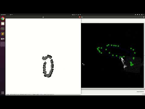
Integration with navigation module using RGBD camera and occupancy grid OctoMap
The navigation module compresses the data from the RGBD camera into an occupancy grid OctoMap. The compressed map constitutes a local map. The local map is projected back to 2D, and navigation is performed on this 2D map.
It is noise robust thanks to its occupancy grid map property and memory efficient thanks to its OctoMap property.


