A repository housing useful models to neatly describe any project in an interview or a conference.
Essentially, when describing any project for someone for the first time, it requires a simplification model to proceed to the ideas, thus far.
Preface: While having a talk with a friend of mine, I stumbled a little while describing what I've achieved so far; I attribute this for the reason that most of my projects involve complex subsets of system engineering that is why they are bulky to describe just in an instant. To know from where you should begin describing a project, you should follow some standard algorithm in thinking. It might be first to describe the problem itself, then a simple non-mathematical physical model; eventually a most in-depth system-model, and if you are in a technical interview, the final model will be a software architectural model. An automata model is rarely required. However, it would serve a good model in conferences.
Vision: Based on the previous experience with building open source software products, formulation of several maneuvers to describe personal and professional projects are attained. Formulations are based on the first order formal logistics and mathematical modelling paradigms for systems and simulation.
- Defining a physical model for the solution and its components; such that the solution subset components would map to the problem components based on the function theory.
- Defining a physical deployment model based on a pruning strategy.
- Defining a system model for the project for the business and companies domain to be used in advertisements and non-technical conferences based on the SES Framework (System-Entity-Structure Framework).
- Defining a discrete mathematical model using the Automata Theory.
- Defining a hybird automata model for analog-digital systems.
This type of modelling is the predominant model in the software engineering industry especially in forward software engineering lifecycles; where a software specification document is required to fulfill the problem, the project goal, the criteria and the standardization of the engineering maneuvers utilized, and finally a software engineering paradigm model.
Note
Essentially, the model is based on the Set Theory, Relations among Sets, and the Function Theory, the following sequential activity is attained:
- A problem domain is synthesized, and an empty problems' set is constructed;
$$P = \{p | p\ is\ a\ problem\ X\}$$ . - The problem set is decomposed further into proper subsets of problems;
$$P = \{S_p | S_p \subset P \}$$ . - Problems are synthesized from a specialized domain (e.g., Railway Engineering - Medicine - Embedded Engineering - Aerospace Engineering ...).
- Properties are synthesized by examining the problems from a specified specialized domain, and assigned to the subsets of problems.
- Problems, previously synthesized and used actively to derive the problems' properties, are grouped into the subsets based on some common properties for the destined proper subsets
$$S_p$$ ;$$S_p = \{ p | p\ is\ a\ problem\ having\ X\ properties \land X\ is\ constructed\ using\ predicate\ calculus\}$$ . - Solutions are synthesized; such that to provide mappings to the problems from the proper subsets
$$S_p$$ based on examining the common properties of these problems. - The type of mappings is described in advance if necessary (e.g., Surjection - Injection - Bijection).
- Types of mappings are described as follows:
- Surjective Mapping (Onto): For each solution in the solution domain (system co-domain), there exists at least one problem.
- Injective Mapping (One-to-one): For each problem in the problem domain, there exists only one solution.
- Bijective Mapping (Onto and one-to-one): For each problem in the problem domain, there exists only one solution, and for each solution in the solution domain (co-domain), there exists at least one problem.
- Solutions' properties are synthesized based on examining the derived solutions, and proper subsets are constructed.
- Solutions are grouped into proper subsets, and solutions' properties are assigned to these subsets.
- A final software architectural paradigm is reached to pattern match it with the common industrial paradigms.
Note
When referring to a deployment model, one should ask a crucial question "What is meant by a deployment, and what are the objects to be deployed so far?".
The answer depends on the context. However, most models will entail defining "deployment model" as the lifecycle to deploy a binary of a project and test it on a specified platform.
A deployment model for a project is commonly used in simple mainly non-technical contexts or as an introductory model for a technical context before delving into much more technical stuff and engineering details related to the problem and the solution domains.
A deployment model could be composed of the following components, commonly managed by a CI/CD container pipeline:
- Development Environment.
- Testing Environment.
- Staging Environment.
- Production Environment.
3) A system model for the business and companies' domains based on SES-Framework with emphasis on deployment:
Copied, by Thorsten Pawletta.
Definition: The System Entity Structure (SES) is a structural knowledge representation scheme introduced by Zeigler. It contains knowledge of decomposition, taxonomy, and coupling of a system. In combination with a Model Base (MB), it supports different concepts for system modeling, investigating design alternatives, reusing good designs, and collaborative modeling.
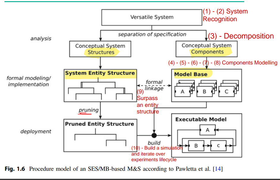
Figure 1.6 shows the general procedure model of an SES/MB-based M&S according to Pawletta et al. Possible configurations of a system or a family of systems are analyzed. That means, basic dynamic components, their relations, and parameter settings are identified. Dynamic components are modeled or implemented as reusable basic systems with defined input and output interfaces and organized in a MB. The possible system structures and parameter settings are modeled with an SES, which specifies formal links to basic systems in the MB.
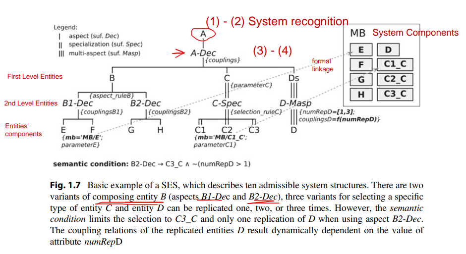
Figure 1.7 shows an example of an SES with associated MB. In the application phase, executable models are generated with transformation methods such as pruning and build. Based on defined objectives, the pruning method derives a unique system configuration from the set of possible configurations. The result of pruning is called Pruned Entity Structure (PES). Based on the information in the PES, the build method generates an Executable Model using basic systems from the MB.
Representation Schema: An SES is represented by a directed tree structure, as illustrated in Fig. 1.7. The different edges are related to different node types. Each node can define attached variables, also called attributes. Real-world or imaginary objects are represented by entity nodes. Entity attributes represent properties of the respective object. The root and the leaves are always entities.
Relations between entities are specified by three types of descriptive nodes, called aspect, multi-aspect, and specialization. The attributes of descriptive nodes specify relations between their parent node and children nodes or decisions for the pruning process.
Relations: Aspects describe how entities can be decomposed in partial entities. Coupling relations can be specified in a couplings attribute. Multi-aspects describe the decomposition of an entity into entities of the same class. They define an additional attribute, called Number of Replications (numRep). The taxonomy of an entity is described by specialization(s) and concerns admissible variants of an entity. Rules for selecting a variant during pruning can be defined in a selection rule attribute. With the extended procedural knowledge representation according to Pawletta et al., attributes can be dynamically assigned values. For example, coupling relations of a multi-aspect can result dependent on the value of attribute numRep.
Semantics: The semantics of the SES is defined by axioms. Types of each node have to follow the axiom alternating mode. Every entity node has to be followed by a descriptive node, and vice versa. A strict hierarchy is needed. In every path of the tree, a name of a node may occur only once. If nodes in different paths have the same name, they need to have the same variables and isomorphic partial trees. This is called uniformity.
Nodes on the same level of a hierarchy, called sibling nodes, have to be valid brothers, meaning that sibling nodes must not have the same name. The axiom of attached variables implies that a node must not have variables of the same name. The axiom of inheritance implies that during pruning, the parent and the child of a specialization combine their variables, aspects, and specializations. The configurations modeled in an SES tree can be delimited by selection constraints and semantic conditions.
Note
There are numerous additional SES concepts, such as using the SES as a general ontology for data modeling, the specification of abstraction hierarchies and time granularities for families of systems, interfaces for automated, reactive pruning, methods for the pruning of deep hierarchies of certain node type combinations, or the combination with performance metrics to evaluate and select the best possible system configurations.
stateDiagram
    state System_Initialization
    state System_Validation
    state User_Input
    state System_Response
    [*] --> System_Initialization

    System_Initialization --> System_Validation: System_Input
    System_Validation --> User_Input: System_Input
    User_Input --> System_Response: System_Input
    System_Response --> [*]: System_Input
Note
The preceding figure is a generalized example for describing some project steps using the abstract mathematical model, the finite-state automata model. A formalization of the model could be attained using the following:
- Let,
$$Q = \{System_{Initialization}, System_{Validation}, User_{Input}, System_{Response}\}$$ be the set of active states, and$$q_0 = \{System_{Initialization}\}$$ be the start or the initial state,$$\Sigma = \{i_0, i_1, i_2, i_3\}$$ be the set of transition inputs,$$\delta: Q \times \Sigma \rightarrow Q$$ be the transition function,$$F = \{System_{Response}\}$$ be the set of accepting states; such that$$f \in Q$$ , and$$F \subseteq Q$$ . - Then, a Machine
$$M$$ could be constructed as a quintuple sequence of members;$$M = (Q, \Sigma, \delta, q_0, F)$$ , and in this particular example, it would be:$$M = (\{System_{Initialization}, System_{Validation}, User_{Input}, System_{Response}\}, \{i_0, i_1, i_2, i_3\}, \delta: Q \times \Sigma \rightarrow Q, \{System_{Initialization}\}, \{System_{Response}\})$$ , and if$$S \subseteq Q$$ and$$\Sigma^* = \{\sigma_{0}\sigma_{1}\sigma_{2}...\sigma_{k} | k, i \in N \land \sigma_{i} \in \Sigma\}$$ is a closure from$$\Sigma$$ ; then,$$\Delta(S, \Sigma^*) = \{\delta(q, \sigma) | \delta(q_i, \sigma_{i+1})_{i+1} \in Q \land i \in [0, k-1]\} = \{q_{i+1} | q_{i+1} \in Q \land i \in [0, k-1]\}$$ is the set of the range (or the co-domain) of the function$$\delta$$ .
The language of the machine
5) A hybird automata model for analog-digital systems (i.e., mixed discrete and continuous systems):
WIP
Examples for projects explained using the Pruned System-Entity-Structure deployment or physical model:
- Body of Knowledge for Modeling and Simulation Tuncer Ören Bernard P. Zeigler Andreas Tolk Editors A Handbook by the Society for Modeling and Simulation, Springer.
- Software Engineering Design by Carlos Otero.
- Guide to Discrete Mathematics, Springer
- Discrete Mathematical Structures by Bernard Kolman.
- NATO ASI Series - Verification of Digital and Hybrid Systems, The Theory of Hybrid Automata, Springer.


