-
Notifications
You must be signed in to change notification settings - Fork 18
Data Placement Strategies
Every Hermes system instance includes one or more Hermes nodes.
A destination is a buffering resource that can be identified by a pair of node + target "coordinates."
Each target
- A capacity
$Cap[t_k]$ - A remaining capacity
$Rem[t_k]$ - A speed (or throughput)
$Speed[...,t_k]$ - This is the mean of the throughputs of all ranks associated with the destination's node.
- Fix this! Speed is really a function of the origin.
Note: At any point in time, there's a degree of uncertainty to some of the destination characteristics. For example, the remaining capacity of a destination is typically obtained from a global metadata (MD) structure that is updated asynchronously. Only the Hermes node buffer pool managers have the precise value(s) for the pool under their management.
Given N storage targets, a data placement policy P, a cost function F, and a BLOB, a data placement consists of a BLOB partitioning and an assignment of those parts to storage targets that satisfies the constraints of the data placement policy and that minimizes the cost function.
- Epoch - interval within which we update targets (status).
- Static (e.g., time interval or number of operations)
- Dynamic, i.e., computed by the delta of status
[optional] Placement window - interval within which we make data placement decisions.
- Timer expired or I/O operation count reached, which ever comes first.
- Static (e.g., time interval or number of operations)
- Dynamic, i.e., number of put operations
Epoch and placement window could be aligned (static mode).
The data placement is done within Data Placement Engine (DPE) component in HERMES.
A placement schema
A sequence of buffer IDs
An allocation of a placement schema is a sequence of buffer IDs which is the concatenation of conforming target assignments.
- Given: a vector of BLOBs
$(b_1, b_2,\ldots, b_B)$ - The DPE creates placement schemas
$PS(b_i),\;1\leq i\leq B$ . - The placement schemas are presented to the buffer manager, which, for each placement schema, returns an allocation of that schema (or an error), and updates the underlying metadata structures.
- I/O clients transfer data from the BLOBs to the buffers.
Input:
- Vector of BLOBs
$(b_1, b_2,\ldots, b_B)$ . - Vector of targets
$(t_1, t_2,\ldots, t_D)$ . - Vector of target remaining capacities
$Rem[t_k], \;1\leq k\leq D$ . - Vector of target speed
$Speed[t_k], \;1\leq k\leq D$ .
Output:
- Placement schema
$(s_1,\ldots,s_k)\mapsto(t_1(s_1),\ldots,t_k(s_k))$ , where$b (>0)$ is a decomposition$b = s_1+\cdots+s_k,\; s_i\in\mathbb{N}\setminus\{0\}$
- Pick a DP solver to obtain a placement schema.
- Linear programming
- Constraints
- Objective function
- Round-robin
- Granularity
- Random
- Distribution(s)
- Linear programming
- Use the buffer pool's "coin selector" to convert into buffer IDs.
- Handle two types of potential errors.
- DP solver failure: This can happen because of outdated target
status, i.e., insufficient capacity, constraint infeasibility,
etc.
- Solution to insufficient capacity: epoch, decision windows, swap space.
- Solution to constraint infeasibility: buffer reorganization, target filtering.
- Coin selection failure: This can happen because of outdated
state view information, e.g., outdated remaining capacities.
- Solution: epoch, decision windows, swap space.
- DP solver failure: This can happen because of outdated target
status, i.e., insufficient capacity, constraint infeasibility,
etc.
In both cases, the list of targets is inappropriate and needs to be updated or changed.
The list of "relevant destinations" for a rank is assembled by the Hermes node topology generator. It gets triggered when DP fails. The initial topology consists of "node-local" destinations (Plan A) plus a backup list of neighbors (Plan B) to consult when a rank gets in trouble. If both plans fail, the topology generator invokes the application-level "rebalancer" to redraw neighborhood boundaries (Plan C). In the past, we used to call these components node- and application-level DPEs, but they aren't directly involved in DP decisions, and we need maybe a clearer terminology.
LP solver
- Pick Google OR-Tools as a linear optimization tool to obtain
a placement schema.
- Minimize client I/O time.
Round-robin solver
- Pick the next target if the remaining capacity is greater or equal to the BLOB size, otherwise check the one after the next target until a target with enough capacity is found.
Random solver
- Randomly pick a target from all targets which have the capacity greater or equal to the BLOB size.
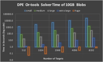
Scaling the number of BLOBs, 10 GB total BLOB size
- Small size BLOBs: random within the range of 4KB to 64KB
- Medium size BLOBs: random within the range of 64KB to 1MB
- Large size BLOBs: random within the range of 1MB to 4MB
- Extra large size BLOBs: random with the range 4MB to 64MB
- Huge size BLOBs: fixed 1GB
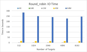
Scaling the BLOB size, 1,000 and 8,192 BLOBs in total
- Fixed BLOB size of 4KB, 64KB, 1MB, 4MB, 64MB
The DPE time of three different solvers with 10GB BLOBs in total.


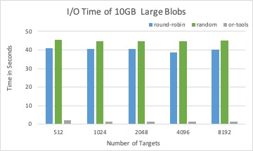
The associated I/O time of placement schema from three different solvers with 10GB BLOBs in total.


The DPE time of three different solvers with 1,000 BLOBs in total.


The associated I/O time by placement schema by three different solvers with 1,000 BLOBs in total.


For a fixed total size of many BLOBs, DPE time is increasing with the number of BLOBs for all solvers.
Round-robin and random solver can quickly calculate targets for a BLOB than LP solver, while not considering optimizing I/O time.
LP solver is efficient when the search space (number of targets) is not too large (for example, less than 1,024).
LP solver is a good candidate to place large size BLOBs, where the DPE time has less impact than the I/O time to the overall performance.
One of the possible policies is that size 64KB could be a boundary for BLOB aggregation. BLOB size less than 64KB will be aggregated within a placement window and than placed together to mitigate DPE impact.
Another possible policy is to use round-robin or random for small blobs and LP solver for large blobs.