| description | title | keywords | image | slug | last_update | |||||
|---|---|---|---|---|---|---|---|---|---|---|
TBD |
TBD |
|
TBD |
XIAO IO |
|
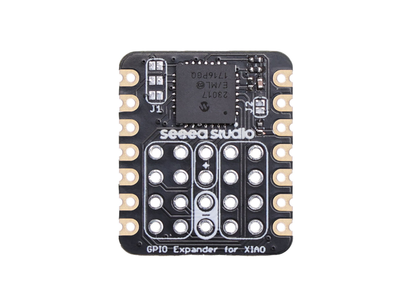
The GPIO Expander for XIAO is a state-of-the-art expansion board designed to enhance the capabilities of the Seeed Studio XIAO series. Powered by the MCP23017 chip, this board offers an additional 16 GPIO pins, allowing users to expand their projects without constraints. Whether you're a hobbyist looking to experiment with more components or a professional seeking a reliable GPIO expansion solution, this board is tailored to meet your needs. Its compatibility with the XIAO series ensures seamless integration, making your development process smoother and more efficient.
- Seamless Integration with XIAO: Designed to work perfectly with the Seeed Studio XIAO series.
- 16 Additional GPIO Pins: Powered by the MCP23017, it provides 16 extra GPIO pins for your projects.
- I2C Interface with Configurable Address: Default I2C address is 0x21, but can be configured to 0x20.
- Robust Design: Built with high-quality materials to ensure longevity and reliability.
- Chip: MCP23017
- Number of GPIO Pins: 16
- Communication Protocol: I2C
- Default I2C Address: 0x21 (Configurable to 0x20)
- Operating Voltage: 3.3V
- Dimensions: 21mm x 17mm
The GPIO Expander for XIAO is versatile and can be used in a multitude of applications, including but not limited to:
- Home Automation Systems: Expand the number of devices you can control in your smart home setup.
- Robotics: Add more sensors, motors, or other components to your robot without running out of GPIO pins.
- Gaming Consoles: Design custom controllers or other peripherals with a plethora of buttons and switches.
- Industrial Control Systems: Manage more devices and sensors in your industrial setup.
- Educational Projects: Teach students about microcontrollers and electronics without being limited by the number of GPIO pins.
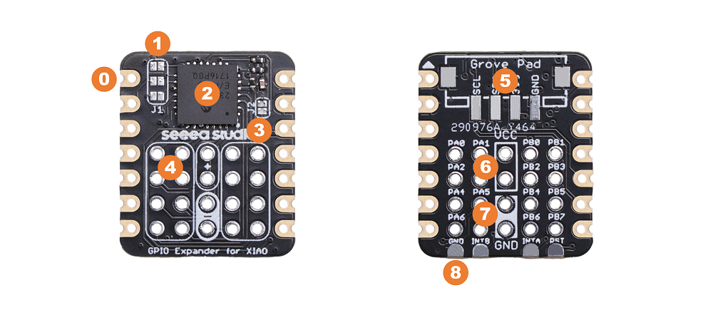
This section provides a detailed overview of the various components and interfaces on the XIAO IO Expander Board.
These are the standard pads for connecting the XIAO microcontroller.
The J1 pads allow users to decide whether to connect the MCP23017's RST, INTB, and INTA pins to the XIAO's D6, D1, and D0 pins through soldering. From top to bottom, they are RST, INTB, INTA.
This is the main I/O expander chip, providing an additional 16 GPIOs.
This pad is for selecting the I2C address. The default address is 0x21. If you solder this pad, the address can be changed to 0x20.
These are the output pins from the MCP23017 chip. Each pin's definition can be seen on the back of the board. They range from PA0 to PB7, providing a total of 16 GPIOs.
If you wish to connect a Grove module, you can solder the provided Grove socket. This Grove interface is connected to the I2C bus.
This is an output pin that can be used to power other components.
This is also an output pin that can be used for grounding other components.
These are some additional output pads, including GND, INTB, INTA, RST. If you wish to solder these pins for use elsewhere, you can do so.
Welcome to the quick start guide for the IO Expander for XIAO. This guide aims to help you set up and get started with your new IO Expander board in conjunction with the XIAO RP2040 main controller.
Upon receiving your product, some soldering will be required. We've provided two pin headers with the package. You'll need to solder these headers onto the expansion board.
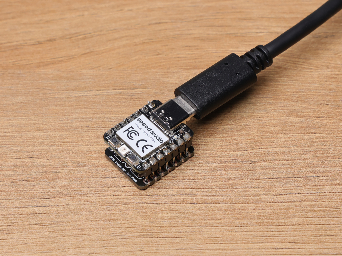
Once the soldering is complete, you can proceed to connect the expansion board to the XIAO RP2040 main controller.
For programming the XIAO RP2040, you'll need a TYPE-C USB data cable. Connect one end to the XIAO RP2040 and the other to your computer. For a detailed guide on programming the XIAO RP2040, please refer to this documentation.
Before you can start programming the LEDs, you'll need a specific library for the RP2040. Download the MCP23017 library from this GitHub link. Once downloaded, install the library in your programming environment.
In the Arduino IDE, open a new sketch and copy the following example code:
#include <Adafruit_MCP23X17.h>
Adafruit_MCP23X17 mcp;

void setup() {
    Serial.begin(9600);
    Serial.println("MCP23xxx Blink Test!");
    if (!mcp.begin_I2C()) {
        Serial.println("Error.");
        while (1);
    }

    Serial.println("Looping...");

    for(int i=0; i<16; i++) {
        mcp.pinMode(i, OUTPUT);
    }
}

void loop() {
    for(int i=0; i<16; i++) mcp.digitalWrite(i, HIGH);
    delay(1000);
    for(int i=0; i<16; i++) mcp.digitalWrite(i, LOW);
    delay(1000);
}
Upload the above code to your XIAO RP2040. Once uploaded, with a multimeter, measure each IO pin. You will see the voltage jump between 3.3V and 0V, consistent with the blinking frequency in the code.
When using single pin operations such as pinMode(pinId, dir) or digitalRead(pinId) or digitalWrite(pinId, val) then the pins are addressed using the ID's below. For example, for set the mode of GPB0 then use pinMode(8, ...). NOTE The MCP23008 and MCP23S08 only have GPAx pins.
| MCP23x17 Pin # | Pin Name | Pin ID |
|---|---|---|
| 21 | GPA0 | 0 |
| 22 | GPA1 | 1 |
| 23 | GPA2 | 2 |
| 24 | GPA3 | 3 |
| 25 | GPA4 | 4 |
| 26 | GPA5 | 5 |
| 27 | GPA6 | 6 |
| 28 | GPA7 | 7 |
| 1 | GPB0 | 8 |
| 2 | GPB1 | 9 |
| 3 | GPB2 | 10 |
| 4 | GPB3 | 11 |
| 5 | GPB4 | 12 |
| 6 | GPB5 | 13 |
| 7 | GPB6 | 14 |
| 8 | GPB7 | 15 |
Answer: Ensure that the XIAO module is correctly plugged into the expansion board. Also, check if the necessary libraries are installed and the correct board and port are selected in the Arduino IDE.
Answer: Yes, the GPIO Expander is designed primarily for the XIAO module, but it can be used with other microcontrollers that support I2C communication. You might need to adjust the code and connections accordingly.
Answer: The default I2C address is set to 0x21. If you want to change it to 0x20, there's a jumper labeled "J2" on the board. You'll need to solder the J2 jumper to change the address.
Answer: Ensure that the connections are secure and there's no interference. Using pull-up or pull-down resistors can help stabilize the input pins. Also, ensure that the power supply is stable and can provide the necessary current for all connected devices.
- [Zip] Eagle file
- [PDF] Datasheet - MCP23017
If you have any technical issue. submit the issue into our forum.


