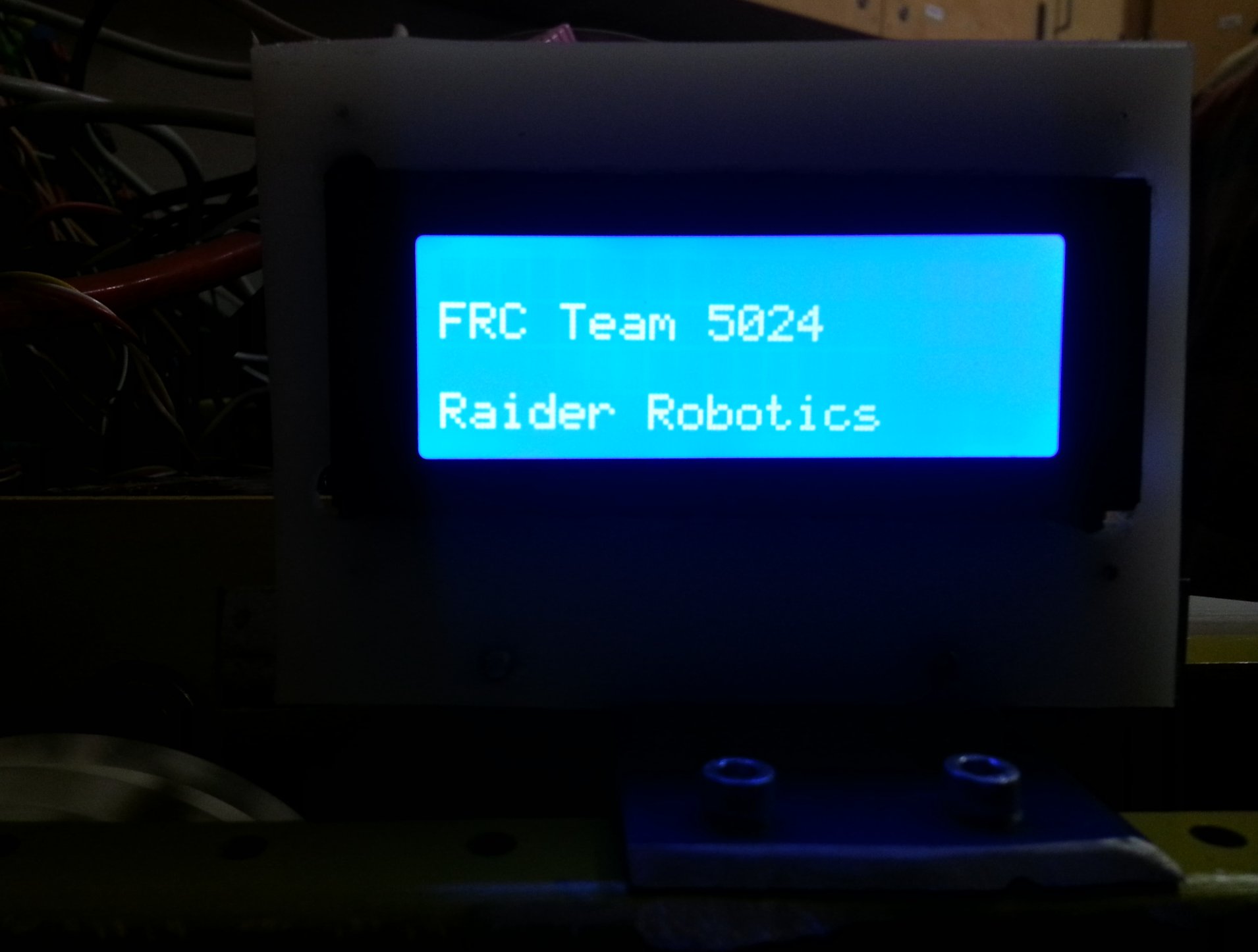
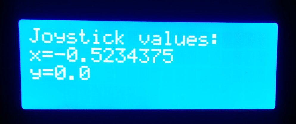
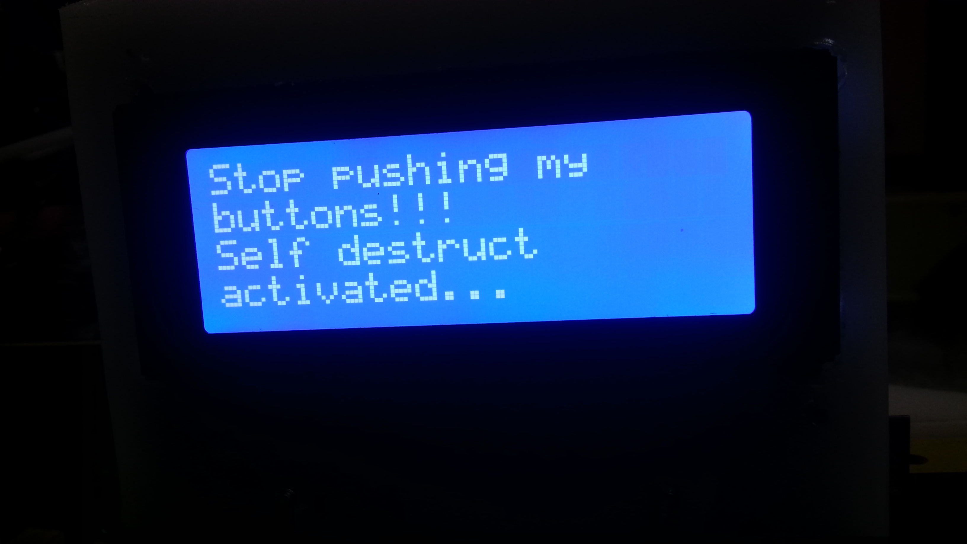
🔷 The source code here demonstrates how to set up a 4x20 LCD panel display with the Roborio (for FRC First Robotics Competition).
All you have to do to use it is add the code that I've written, and then run the command LCDwriteString(String s, int line); where String s is the string to write to the display, and int line is line number (1-4).
▪️ We're using a display like the one in the photo
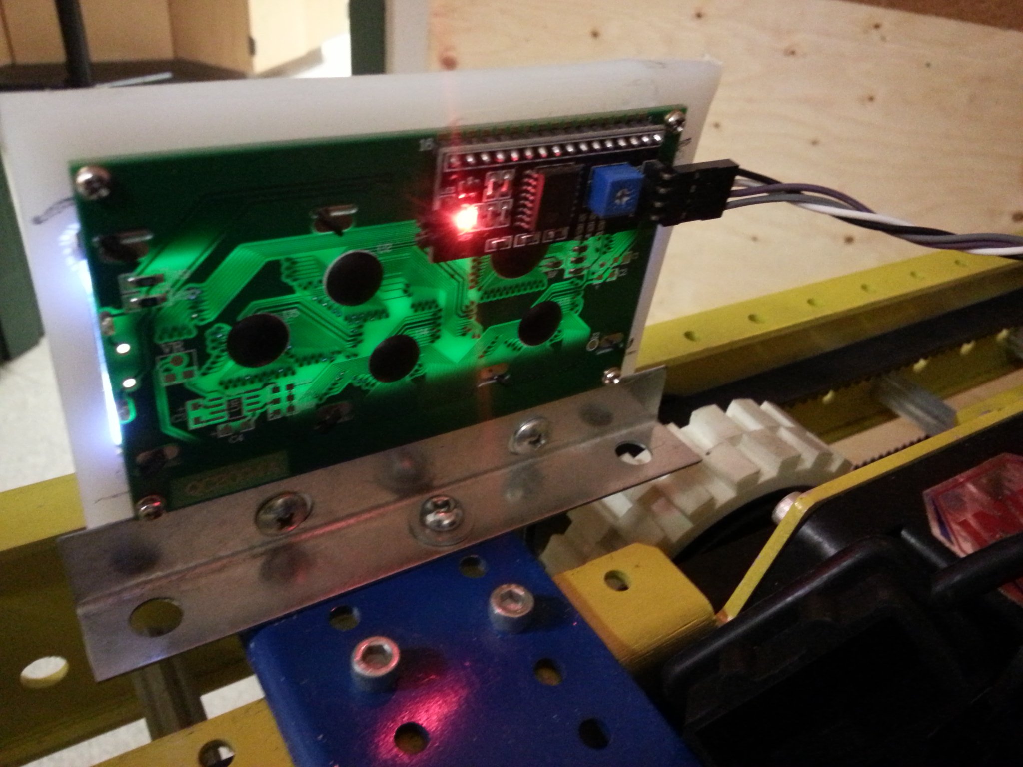
▪️ Note that it comes with a backplate thing mounted on it. This backplate already has all of the connections between the LCD display and the I2C protocol.
▪️ The connectors on the back of the LCD display do not match the connectors on the RoboRIO. The RoboRIO has the pins in a different order. Also note that the LCD display requires 5V, not the 3.3V on the RoboRIO I2C connector. We're just using 5V from a digital IO pin. You could also use the 5V from the Voltage Regulator Module.
💥 WPI Documentation The WPI documenation is completely useless. The source code is no help either.
It's easy to make an I2C object: lcdDisplay = new I2C(I2C.Port.kOnboard, 0x27); The address of most LCD panels is 0x27. It's a lot harder to write to the display since the only thing that the documentation tells you is boolean write (int registerAddress, int data). There is no explanation of what the register address should be, no examples of this being used anywhere. (I finally figured it out, see below.)
💥 LCD Panels are all driven by the Hitachi HD44780 driver. This page provides details, explains the display addressing, and lists the commands that are build in.
💥 There are some very useful code examples here:
- LCD panel display documentation: http://www.microcontrollerboard.com/lcd.html
- Using Java to access I2C devices with examples of LCD display: https://docs.oracle.com/javame/8.1/me-dev-guide/i2c.htm
- This helped understand the hardware a bit. http://letsmakerobots.com/content/drive-standard-hd44780-lcd-using-pcf8574-and-i2c
💥 Finally, I realized that my python code 🐍 (which I got from someone else's Raspberry Pi repository) could be directly ported to Java. It worked!!!
- It turns out that the register to write the I2C data is ALWAYS 0 (I'm talking about the WPI
I2C.write()command). Why? This is either the I2C controller or the register on the I2C device. So it seems that the LCD display only has one (external facing) register. - However ... internally, there are TWO registers: a command register and a data/display register. The registers are INTERNAL and are selected by using the Rs bit or not.
- Commands are always written 4 bits at a time. Why? This is because it's the way that everyone does it. (Originally it was so that you need fewer data lines connected to your display.)
- Commands have to be "strobed" using the En bit for them to take effect.
- Commands do not execute instantaneously, so you need a short delay between them.
- There is a sequence of initialization commands that must be done to set up the display after it's been powered on before it can be used.
- Many of the other commands (cursor movement, etc.) I have not tried.


