-
Notifications
You must be signed in to change notification settings - Fork 0
Analog Spy
There are some ways to do serial communication with the ATtiny but all of them involve a shitload of work.
A more lightweight way of communication a value can be achieved with this sketch. It flashes a value between 0 and 1023 to you through attached LEDs. Port 0 communicates the high bits and port 1 communicates the low bits.
After the setup of the sketch is complete, the value of the analog port is communicated over and over.
You write down a '1' for a DP0 LED flash and a '0' for a DP1 LED flash. This will result in a 10-bit binary number. If you do not speak binary (e.g. you do not know that 1 + 1 = 10) then search the web for binary to decimal conversion and enter the 10 bits binary number to get the decimal value.
The start sequence flashes both LEDs three times. This is an indication that the next sequence is a binary value.
- Play the start sequence
- Test 5 low bits (LED 2 flashes 5 times)
- Play the start sequence
- Test 5 high bits (LED 1 flashes 5 times)
- Play the start sequence
- Signal the analog value from analog port 3
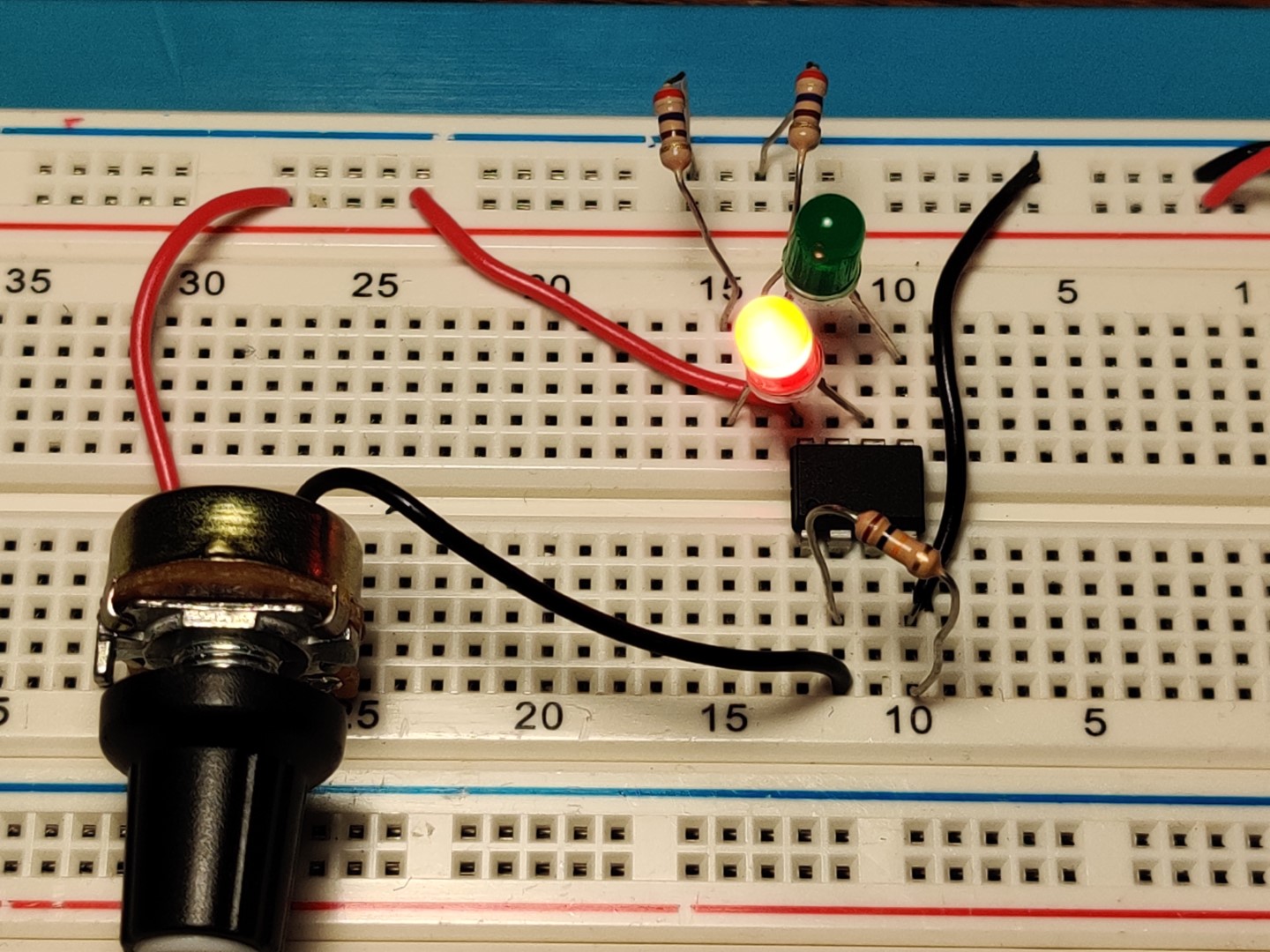
- The analog measuring device (a potentiometer) between +5v and AP3
- A 10K+ pulldown resistor between AP3 and GND.
- Green LED between DP0 and GND through a current limiting resistor.
- Red LED between DP1 and GND through a current limiting resistor.
