Arduino-based project to make a tournament display for speedcubing and speedstacking that is compatible with all major timers. Uses MAX7219 driven LED matrices as the display.
First assemble the hardware according to the schematics. A full tutorial will be up shortly. Instructions given below are for the software only.
- Install the Arduino IDE.
- Download the libraries MD_Parola and MD_MAX2XX using 'Clone or download' -> 'Download ZIP'.
- Extract the ZIPs to get two folders called MD_Parola-master and MD_MAX72XX-master.
- Move these folders to the Documents\Arduino\Libraries folder (On Windows only. more info on library installation can be found here)
- Open MD_MAX72XX-master\src\MD_MAX72XX.h. If it does not display well in notepad, try wordpad.
- Search for USE_PAROLA_HW and replace the 1 next to it with a 0. Search for your hardware (usually USE_FC16_HW, see the full tutorial for more information) and replace the 0 next to it with a 1. Save the file and close it.
- Download this repository and extract the ledmat.ino file. Open it, set the board to Arduino Nano in the Tools menu. Also make sure the correct Port is selected.
- Upload the sketch, plug in the stackmat and enjoy!
- Setup github actions to run
make all check(Pedro) - Translate the JS bitstream processor into C for the arduino
- code first prototype of working display
- add code snipets and examples throughout timer signal protocol
- think of a better name for the project?
- github dirtywork - ending fork? and fixing origin on c-processor branch
- (André) fix lints
- (Pedro) finish coding processor.c
- (André) reading bitstream from audio jack to input into processor.c
- (Pedro) read result from processor.c and display in led matrix (MD_PAROLA, etc.) - we don't need to display thousands of seconds - take code from ledmat
- (Pedro) encasing and power (maybe powerbank) prototype for hardware
- we could show the state before the start of the attempt instead of just zeros - show when hands are on timer, when competitor is ready
- instead of displaying 0:00.00 format from the getgo, we could start display only the three rightmost digits and add the other ones as needed while the timer keeps running
- the Gen 5 timer has an annoying feature that, when in 2-pad mode, it switches off and on three times after the timer is stopped, which is reproduced on the display, we should try to avoid this behaviour
- never display thousands of seconds - not used in WCA competitions
The Speedstacks timers send a digital audio signal thorugh the data port (example). This is a guide how on to interpret the signal.
The timer sends the signal with a fixed rate of 1200 bits per second (check if this is correct and consistent across all timer generations). It sends a packet that are 90 or 100 bytes long to convey a single time to be displayed.
The bitstream user a standard idle value (0 or 1) to inform when a byte or a packet ended. The idle value varies across timer generations (see section below on timer generations).
Each byte is proceeded by a non-idle value, to show that the byte has begun, and followed by an idle value, to show that it has ended.
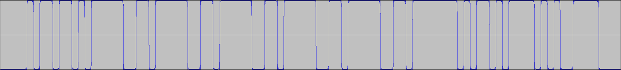

Each packet is separated by an unspecificed number of idle values (check if we can tell an exact amount and if it is consistent across timers). Therefore, to check if a packet has ended, you just need to check if you can read ten or more equal values in a row, as that couldn't happen if a byte was being transmitted.
A time to be displayed is sent as a packet that can be 9 or 10 bytes long. The lenght of the packet is determined by the timer generation (see section below on timer generations).
Because of the non-idle value and idle value that go before and after each byte, the bytes take 10 bits to be transmitted, and the packet lenghts are therefore 90 or 100 bits.
Here is an example of a full packet extracted from a Gen 3 timer that will use to break down what each byte means. TODO
Notice that this packet it 10 bytes long and uses 1 as its idle value.
These are what each byte consists of:
The first byte is an ASCII code for one of the following letters, which represent the state the timer is in:
- "L" (Left hand on timer)
- "R" (Right hand on timer)
- "C" (Both hands on timer)
- "A" (Ready to start)
- "I" (Reset)
- "S" (Stopped)
- " " (Running and no hands on sensor)
These are the bytes that convey the time information. Byte 7 may or may not be a part of this depending on the timer generation (see section below on timer generations).
Here is the breakdown on byte-by-byte:
- 2: minutes
- 3: tens of seconds
- 4: units of seconds
- 5: tenths of a second
- 6: hundreths of a second
- 7 (if in use): thousands of a second (check - if 7th byte no used to convey time information, does timer simply not transmit thousands of a second?)
The byte represents the ASCII code for the digit, which is the digit + 48
This byte is a checksum of the previous bytes (2-6 or 2-7), to ensure the reading is correct.
It it the sum of the values (not the ASCII codes) of all digits + 64.
These bytes are the ASCII codes for \n (newline) and \r (carriage return). Is this just useless?
After reading the 10 bits necessary for a byte (non-idle value + byte + idle value), you must first discard the 1st and the last bits of the byte.
Then, you must place the bits in reverse order. E.g. (11001001 becomes 10010011)
Finally, the bits must be inverted to arrive at the final byte (10010011 becomes 01101100). do timers with a 0 idle value also need to be inverted?
WIP

- Packet length: 10 bytes
- Idle value: 1

- Packet length: 9 bytes (dobule check)
- Idle value: 0 (double check)

- Packet length: need to check
- Idle value: 1 (double check)
can we easily support other non-speedstacks timers? testing needed
TODO
on the TRRS jack, we use only the sleeve for GND and the tip connected to any digital pin
TODO
git ls-files | entr -cs "make -j12 all check"
- Odder's Stacktimer Signal Processor link: reference on how to process the stackmat signal bitstream (for Gen 4 timers)
- JFly's explanation on the speedstacks timer signal and reading it in a phone
- freundTech's explanation on what the speedstacks timer signal bitstream is composed of
- Dan Smith testing what causes reset issues in Gen 5 timers
- Coding experiments on forum
- Wiring a MAX7219 LED Dot Matrix
- Getting started with MD Parola
- Old stackmat display project
- https://docs.arduino.cc/built-in-examples/arduino-isp/ArduinoToBreadboard
- https://www.martyncurrey.com/arduino-atmega-328p-fuse-settings/
- https://www.instructables.com/Configure-Arduino-IDE-for-Atmega-328P-to-Use-8MHz-/
- https://www.instructables.com/USBASP-Bootloading-a-ATMega328p-with-a-8mhZ-intern/