Home

This application has been hosted on SourceForge as part of Physics and Math Applets project, then used to be a part of Ultrastudio.org FOSS applet collection. It has been first written in 2009 by Carlo Baraco as series of Java applets, later modified by various authors and eventually ported to Android. It is also part of F-droid project.
Copyright (C) Carlo Baracco, Audrius Meskauskas (code, GPL), User:Batholith (glass images, PD), Joao Estevao Andrade de Freitas (feather, PD), User:Pi (ghost, PD), prism image Popular Science Monthly Volume 5 (1874, PD), images modified.
This program is Free software: you can redistribute it and/or modify it under the terms of the GNU General Public License as published by the Free Software Foundation, either version 3 of the License, or (at your option) any later version.
Ray diagram is a method to determine the light path from light source (or observed object) through lenses or mirrors till screen, human eyes or other observer. Ray diagrams have been important in the past and are still useful to understand how does the optical systems work.
Mirrors and lenses normally have the circular symmetry. The axis of this symmetry is called the principal axis. The ray, following the path of the principal axis passes the lens without altering its path. For mirror, such ray is directly reflected back. As both mirrors and lenses are curved surfaces, they have the centre of the curvature located on the principal axis (marked C in the diagrams). The point between centre of the curvature and the mirror (or lens) is called the focal point (marked F).
Ray diagram is build following the two simple rules:
- Any ray parallel to the principal axis will bend upon reflection or refraction so that either the ray itself or its continuation passes through the focal point (for symmetric lenses, one of the two focal points located by the same distance F from the lens on both sides).
- If the ray or its continuation passes through the focal point, after reflection or refraction it will travel parallel to the principal axis. It is often approximated that the lens is thin enough not to take effects of its volume into consideration. This approximation if good enough for most of the lenses. Taking lens thickness into consideration results more complex analysis that is currently not covered in this article.
Converging lens bends rays toward they optic axis and is able to focus parallel rays to the single point where the screen (as in cinema) or photo-sensing matrix (as in camera) can be placed to capture the image. Such image is called the real image. For object beyond (more distant than) the focal point, the convex lens produces the real image. This image appears on the opposite site of the lens, and its is turned "upside down". Human eye also uses single concave lens that produce the "upside down" picture in the retina, and brain later to transforms it back to the original orientation. Convex lens bends parallel rays so that they all later meet at the focal point. However if the object is between the lens and the focal point, the convex lens produces originally oriented, virtual image (explained in next chapter). This image is enlarged, so the convex lens is also a "magnifying glass".
Diverging lense cannot focus rays this way as it bends rays away from they optic axis. However bending rays away from the optic axis means that the continuations of the ray met on the other side of the lens, focusing so called virtual image. The virtual image cannot projected into screen but it can be seen by human eye, photo camera or other device with its own optical system that could focus the rays. It is located at the same side of the lens as the object itself (this is where the ray continuations met) and has the original orientation (not upside down). It can be seen by eye or camera if looking from the opposite side through the lens. Corrective lenses that many people wear to compensate myopia are concave lenses, so they present virtual images against the myopic eye. Such eye can see them even better than real ones.
Converging mirror has a reflecting surface that bulges inward, away from the incident light. It focuses rays in a more complex way, depending on the distance between the object and mirror[7]. If the object is between the focal point and mirror, the mirror produces magnified, originally oriented virtual image. If the object is exactly at the focal point, the mirror does not produce any image (it would focus on infinity). If the object is between the focal point and centre of the mirror curvature (located in a double distance of the focal point from the mirror), it produces inverted (upside down), magnified real image. If the object is exactly at the centre of the curvature, it produces inverted real image of the same size. For the object beyond the centre of the curvature, the mirror produces inverted real image that is smaller in size than the original image. Converging mirror reflects parallel rays so that they all meet at the focal point.
Diverging mirror (also called fisheye mirror) has a reflecting surface that bulges outward (like a polished ball). Such mirror always forms virtual image, as both its focal point and center of the curvature lie behind the mirror, in the "imaginary space". The image is always smaller that the original one and keeps the same orientation. Convex mirror gives the wider view angle than the flat mirror, and is often used where this wider angle is required. When important (as in the car mirrors) it contains the safety label that reflected objects look more distant than they are. Same as for the convex lens, reflected virtual images can be easily seen by human eye. Due ability to focus parallel rays convex lenses and mirrors are also called converging lenses and mirrors, and they opposite counterparts are called diverging lenses and mirrors.
In all ray diagrams, use the single touch or drag to change the position of the object. The thick green lines show the path of the real rays that could produce the real image. The ray continuations, where important, are extended in the thin green lines and some other important continuations are painted in magenta. When the produced image is virtual, a tiny ghost appears next to it. Touching in two locations at the same time sets the focus distance to the distance between the touching points. Touch in three points to switch between white and monochrome light.
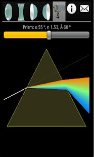
Prism is a transparent optical element with flat, polished surfaces that refract light. In the usual triangular prism, the ray changes direction twice, one time when it enters the prism and second time when it leave the prism. The prism form is such that both times the ray is bended toward the same direction, and the total deviation angle is the sum of these two deviation angles. If the final angle exceeds 90 degrees (with relate to the exit surface), the ray cannot leave the prism - it stops conducting light.
Use the top slider to change the optical density of the material, single touch to alter the ray angle and the "zoom" gesture to reshape the prism, observing, how there three parameters change the ray path and the final deviation angle.