A NES (Nintendo Entertainment System) emulator with SD card and menu support for the Raspberry Pi Pico, Raspberry Pi Pico 2 and other RP2040/RP2350 based microcontrollers. Uses HDMI for display.
Supports two controllers for two player games. See "about two player games" below for specifics and limitations
The emulator used is Infones by Jay Kumogata which was ported to the Raspberry Pi Pico by Shuichi Takano with changes done by me to accomodate the SD card menu.
Create a FAT32 formatted SD card and copy your NES roms on to it. It is possible to organize your roms into different folders. Then insert the SD Card into the card slot. Needless to say you must own all the roms you put on the card.
A menu is added to the emulator, which reads the roms from the SD card and shows them on screen for the user to select, flash and play.
See below for possible configurations, supported game controllers and how to setup. There is even a custom PCB (printed circuit board) available and a 3D-printable case design which fits the PCB.
There is also an emulator port for the Sega Master System/Sega Game Gear and DMG Game Boy. You can find them here:
- Sega Master System/Game Gear: https://github.com/fhoedemakers/pico-smsplus
- DMG Game Boy: https://github.com/fhoedemakers/pico-peanutGB
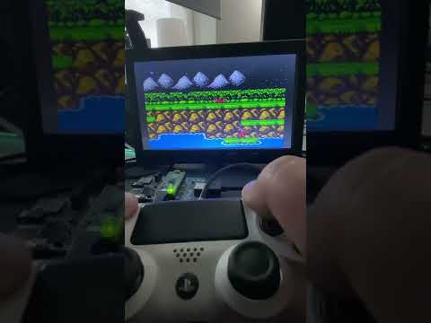
Click on image below to see a demo video.
You can use it with these RP2040/RP2350 boards and configurations:
-
Raspberry Pi Pico or Pico 2. Requires one of these addons:
-
Pimoroni Pico DV Demo Base hdmi add-on board. For use with a USB gamecontroller or up to two a legacy NES controllers. (NES controller ports require soldering)
-
Breadboard and
For use with a USB gamecontroller or up to two legacy NES controllers. (No soldering requirerd)
-
A custom printed circuit board (PCB) designed by @johnedgarpark. (requires soldering) Up to two NES controller ports can be added to this PCB. Can also be used with a USB gamecontroller. You can 3d print your own NES-like case for the PCB.
-
-
Adafruit Feather RP2040 with DVI (HDMI) Output Port. For use with a USB gamecontroller, up to two legacy NES controllers, or even a WII classic controller. Requires these addons:
- Breadboard
- SD reader (choose one below)
- Adafruit Micro-SD breakout board+.
- FeatherWing - RTC + SD. (not tested by me, but should work)
-
Waveshare RP2040-PiZero Development Board
For use with a USB gamecontroller, up to two legacy NES controllers, or a WII classic controller. (No soldering requirerd)
You can 3d print your own NES-like case for for this board. This does require some soldering.
See below to see how to setup your specific configuration.
Note
It seems that sellers on AliExpress have copied the PCB design and are selling pre-populated PCB's. I do not condone this in any way. For questions about those boards, please contact the seller on AliExpress.
Depending on the hardware configuration, the emulator supports these gamecontrollers:
- Sony Dual Shock 4
- Sony Dual Sense
- BUFFALO BGC-FC801 connected to USB - not tested
- Genesis Mini 1 and 2
- PlayStation Classic
- Keyboard
- XInput type of controllers like Xbox 360 and Xbox One controllers and other XInput compatible controllers like 8bitDo.
- Mantapad, cheap NES and SNES USB controllers from AliExpress. Although cheap and working i do not recomended them.
See also troubleshooting USB controllers below
Note
There is some input lag when using USB controllers.
- One or optional two original NES controllers for two player games. In some configurations, soldering is required.
- WII-classic controller: Adafruit Feather RP2040 and WaveShare RP2040 Pi-Zero boards only
Parts list for legacy controllers
-
NES Controller. A second controller port and controller is optional and only needed if you want to play two player games using NES controllers. Two player games can also be played with a USB controller and a NES controller.
-
WII-Classic controller
- Adafruit Wii Nunchuck Breakout Adapter - Qwiic / STEMMA QT
- Adafruit Feather RP2040: Adafruit STEMMA QT / Qwiic JST SH 4-pin Cable
- Waveshare RP2040-PiZero Development Board: STEMMA QT / Qwiic JST SH 4-pin Cable with Premium Female Sockets
- WII Classic wired controller
The emulator supports two player games using two NES controllers or an USB gamecontroller and a NES controller.
Note
You cannot use two USB controllers for two player games. At the moment only one USB controller is recognized by the driver. In this case the USB controller is always player 1. Player 2 must be a NES controller.
| Player 1 | Player 2 | |
|---|---|---|
| USB controller connected | USB | NES port 1 or NES port 2 |
| No usb controller connected | NES port 1 | NES port 2 |
Repeatedly flashing your Pico will eventually wear out the flash memory.
The emulator overclocks the Pico in order to get the emulator working fast enough. Overclocking can reduce the Pico's lifespan.
Use this software at your own risk! I will not be responsible in any way for any damage to your Pico and/or connected peripherals caused by using this software.
I also do not take responsability in any way when damage is caused to the Pico or display due to incorrect wiring or voltages.
Click on the link below for your specific board configuration:
- Raspberry Pi Pico or Pico 2, setup for Pimoroni Pico DV Demo Base
- Raspberry Pi Pico or Pico 2, setup with Adafruit hardware and breadboard
- Adafruit Feather RP2040 with DVI (HDMI) Output Port setup
- Waveshare RP2040-PiZero Development Board
- Printed Circuit Board (PCB) for Raspberry Pi Pico or Pico 2
- Raspberry Pi Pico or Pico 2 with soldered male headers.
- Pimoroni Pico DV Demo Base.
- Micro usb to usb OTG Cable
- Controllers (Depending on what you have)
- Dual Shock 4 or Dual Sense Controller.
- one or two NES Controllers.
- NES controller port. Requires soldering.
- An original NES controller
- Optional: A sconde NES controller port and controller if you want to play two player games.
- Dupont wires
- Mail or female headers to be soldered on the board
- HDMI Cable.
- Micro usb power adapter.
- Micro usb to usb cable when using the Duak Shock 4 controller
- USB C to USB data cable when using the Sony Dual Sense controller.
- FAT 32 formatted Micro SD card with roms you legally own. Roms must have the .nes extension. You can organise your roms into different folders.
- When using a Pico / Pico W, download pico_piconesPlusPimoroniDV.uf2 / pico_w_piconesPlusPimoroniDV.uf2 from the releases page.
- When using a Pico 2 or Pico 2 W, download pico2_piconesPlusPimoroniDV.uf2 from the releases page.
- Push and hold the BOOTSEL button on the Pico, then connect to your computer using a micro usb cable. Release BOOTSEL once the drive RPI-RP2 appears on your computer.
- Drag and drop the UF2 file on to the RPI-RP2 drive. The Raspberry Pi Pico will reboot and will now run the emulator.
| Port 1 | Port 2 (optional) | Note | |
|---|---|---|---|
| GND | GND (- on board) | ||
| VCC (Power) | Connect to 3V3 | ||
| NES Clock | GPIO14 | GPIO1 | |
| NES LATCH | GPIO16 | GPIO20 | |
| NES Data | GPIO15 | GPIO21 |
Note
Soldering is required. There is only one 3v3 pin header on the board, the other 3V3 must be soldered directly onto pin 36 (3V3 OUT) of the Pico. For GND there are two pin headers available on the board. Clock Data and Latch for NES controller port 1 must be soldered directly onto the Pico. The Clock, Data and Latch for NES controller port 2 can be soldered on the available pin headers on the board, no need to solder them directly onto the Pico.


- Disconnect the Pico from your computer.
- Attach the Pico to the DV Demo Base.
- Connect the HDMI cable to the Demo base and your monitor.
- Connect the usb OTG cable to the Pico's usb port.
- Depending which controller you want to use:
- Connect the controller to the other end of the usb OTG.
- Connect legacy NES controller(s) to NES controller port(s).
- Insert the SD card into the SD card slot.
- Connect the usb power adapter to the usb port of the Demo base. (USB POWER)
- Power on the monitor and the Pico

In this image the NES controller port is wired to port 2.
For single player games: use USB controller.
For two player games: Connect a USB controller for player 1 and a NES controller for player 2.

Controller port 1 pins must be soldered directly onto the Pico.
Controller port 2 pins can be soldered to the available headers of the Pimoroni DV.
For two player games:
- Connect two NES controllers or
- Connect a USB controller for player 1 and a NES controller for player 2. You can use either NES controller ports.
NOIMAGE - TODO
- Raspberry Pi Pico or Pico 2 with soldered male headers.
- Adafruit DVI Breakout For HDMI Source Devices
- Adafruit Micro-SD breakout board+
- Micro usb to OTG Y-Cable
- Breadboard
- Breadboard jumper wires
- Controllers (Depending on what you have)
- one or two NES controllers.
- Dual Shock 4 or Dual Sense Controller.
- HDMI Cable.
- Micro usb power adapter.
- Usb C to usb cable when using the Sony Dual Sense controller.
- Micro usb to usb cable when using a Dual Shock 4.
- FAT 32 formatted Micro SD card with roms you legally own. Roms must have the .nes extension. You can organize your roms into different folders.
- When using a Pico / Pico W, download pico_piconesPlusAdaFruitDVISD.uf2 / pico_w_piconesPlusAdaFruitDVISD.uf2 from the releases page.
- When using a Pico 2 or Pico 2 W, download pico2_piconesPlusAdaFruitDVISD.uf2 from the releases page.
- Push and hold the BOOTSEL button on the Pico, then connect to your computer using a micro usb cable. Release BOOTSEL once the drive RPI-RP2 appears on your computer. Or when already powered-on. Press and hold BOOTSEL, then press RUN on the board.
- Drag and drop the UF2 file on to the RPI-RP2 drive. The Raspberry Pi Pico will reboot and will now run the emulator.
See https://www.raspberrypi.com/documentation/microcontrollers/images/pico-pinout.svg for the pinout schema of the Raspberry Pi Pico.
Use the breadboard to connect all together:
- Wire Pico Pin 38 to the breadboard ground column (-)
- Wire the breadboard left ground column (-) with the breadboard right ground column (-)
| Breakout | GPIO | Note |
|---|---|---|
| CS | GPIO5 | |
| CLK (SCK) | GPIO2 | |
| DI (MOSI) | GPIO3 | |
| DO (MISO) | GPIO4 | |
| 3V | Pin 36 (3v3 OUT) | |
| GND | Ground on breadboard (-) |
| Breakout | GPIO | Note |
|---|---|---|
| D0+ | GPIO12 | |
| D0- | GPIO13 | |
| CK+ | GPIO14 | |
| CK- | GPIO15 | |
| D2+ | GPIO16 | |
| D2- | GPIO17 | |
| D1+ | GPIO18 | |
| D1- | GPIO19 | |
| 5 (*) | VBUS | Pin 40 (5volt) |
| GND (3x) | Ground on breadboard (-) |
(*) This is the via on the side of the board marked 5. (next to via D and C).

| Port1 | Port 2 (optional) | Note | |
|---|---|---|---|
| GND | |||
| VCC (Power) | (3v3 OUT) | ||
| NES Clock | GPIO6 | GPIO9 | |
| NES LATCH | GPIO8 | GPIO11 | |
| NES Data | GPIO7 | GPIO10 |
- Disconnect the Pico from your computer.
- Attach the Pico to the breadboard.
- Insert the SD card into the SD card slot.
- Connect the HDMI cable to the Adafruit HDMI Breakout board and to your monitor.
- Connect the usb OTG Y-cable to the Pico's usb port.
- Connect the Micro usb power adapter to the female Micro usb connecter of the OTG Y-Cable.
- Controllers (Depending on what you have)
- Connect the USB-controller to the full size female usb port of the OTG Y-Cable.
- Connect your NES controller(s) to the NES controller port(s).
- Power on the monitor and the Pico
See image below.
Note
The Shotky Diode (VSYS - Pin 39 to breadboard + column) and the wire on breadboard left (+) to right (+) are not necessary, but recommended when powering the Pico from a Raspberry Pi. See Chapter 4.6 - Powering the Board of the Raspberry Pi Pico Getting Started guide
In this image the NES controller port is wired to port 1.
For single player games, connect either an USB controller or a NES controller. Not both!
For two player games: Connect a USB controller for player 1 and a NES controller for player 2.

Choose either of the following:
- Connect two NES controllers
- Connect a USB controller for player 1 and a NES controller for player 2. You can use either NES controller ports.
Note
The device on the left is a Pico Debug probe used for debugging. This is optional

- Adafruit Feather RP2040 with DVI (HDMI) Output Port
- SD Reader (Choose one below)
- Adafruit Micro-SD breakout board+ together with a breadboard.
- FeatherWing - RTC + SD - not tested by me, but should work.
- Breadboard
- Breadboard jumper wires
- USB-C to USB data cable.
- HDMI Cable.
- FAT 32 formatted Micro SD card with roms you legally own. Roms must have the .nes extension. You can organise your roms into different folders.
- Optional: a push button like this.
When using a USB gamecontroller this is needed:
- USB C male to micro USB female cable
- Micro usb to OTG Y-Cable
- Micro usb power adapter
- Usb C to usb cable when using the Sony Dual Sense controller.
- Micro usb to usb cable when using a Dual Shock 4.
When using legacy controllers, this is needed:
- USB-C Power supply
- Depending on what you have:
- one or two NES Controllers.
- WII-Classic controller
See: https://learn.adafruit.com/assets/119662 for the Feather pin scheme.
Use the breadboard to connect all together:
- Wire the 3.3V Pin to the breadboard + column.
- Wire the GND Pin to the breadboard - column
- Wire the breadboard left ground column (-) with the breadboard right ground column (-)
- Optional: Attach a push button to the breadboard and connect a wire from this button to the Feather RST pin and breadboard ground column(-). This adds an extra easy to access Reset button.
| Breakout | GPIO | |
|---|---|---|
| CS | GPIO10 | |
| CLK (SCK) | GPIO14 | |
| DI (MOSI) | GPIO15 | |
| DO (MISO) | GPIO8 | |
| 5V | USB | pin labelled USB on feather |
| 3V | See Note below | |
| GND | - column on breadboard connected to feather ground pin |
Note
The Adafruit Micro-SD breakout board+ has also a 3V input pin which can be connected to + column on breadboard connected to feather 3.3V pin. However, this gave me frequently errors trying to mount the SD card. So use 5V in stead.
Connect the nunchuck breakout adapter to the Feather DVI using the STEMMA QT cable.
| Port 1 | Port 2 (optional) | Note | |
|---|---|---|---|
| GND | - column on breadboard connected to feather ground pin | ||
| VCC (Power) | + column on breadboard connected to feather 3.3V pin | ||
| NES Clock | GPIO5 | GPIO26 | |
| NES LATCH | GPIO9 | GPIO27 | |
| NES Data | GPIO6 | GPIO28 |
- Download pico_piconesPlusFeatherDVI.uf2 from the releases page.
- Connect the feather to a USB port on your computer using the USB-C data cable.
- On the feather, push and hold the BOOTSEL button, then press RESET. Release the buttons, the drive RPI-RP2 should appear on your computer.
- Drag and drop the UF2 file on to the RPI-RP2 drive. The Raspberry Pi Pico will reboot and will now run the emulator.
Note
When the emulator won't start after flashing or powering on, and the screen shows 'No signal,' press the reset button once again. The emulator should now boot.
- Disconnect the Pico from your computer.
- Attach the Adafruit Feather RP2040 DVI to the breadboard.
- Insert the SD card into the SD card slot.
- Connect the HDMI cable to the HDMI port of the Adafruit Feather and to your monitor.
- Connect controllers depending on your setup:
- Legacy controllers.
- NES Controller to the NES controller port.
- WII-Classic controller to the Nunchuck Breakout Adapter.
- Connect USB-C power supply to USB-C connector.
- USB game Controllers
- Connect the USB C connector of the "male USB C to female micro usb cable" to the USB C port of the feather.
- Connect the female micro USB port of the "male USB C to female micro usb cable" to the male micro USB port of the USB OTG Y cable.
- Connect the Dual Sense or Dual Shock controller with the appropriate cable to the full size female usb port of the OTG Y-Cable.
- Connect the Micro usb power adapter to the female Micro usb connecter of the OTG Y-Cable.
- Legacy controllers.
- Power on the monitor and the Pico
In this image the NES controller port is wired to port 1.
For single player games, connect either an USB controller or a NES/WII-classic controller. Not both!
For two player games: Connect a USB controller for player 1 and a NES or WII-Classic controller for player 2.

Image: Two player setup using two NES controllers or a USB controller and a NES/WII-classic controller
Choose either of the following:
- Connect two NES controllers
- Connect a WII-Classic Controller for player 1 and a NES-Controller on port 2 for player 2
- Connect a USB controller for player 1 and a NES controller for player 2. You can use either NES controller ports. You can also use the WII-classic controller for player 2.

- Waveshare RP2040-PiZero Development Board.
- USB-C to USB-C - USB-A Y cable. (when using an USB controller)
- USB-C to USB-A cable for flashing the uf2 onto the board.
- USB-C Power supply. Connect to the port labelled USB, not PIO-USB. See note below.
- Mini HDMI to HDMI Cable.
- FAT 32 formatted Micro SD card with roms you legally own. Roms must have the .nes extension. You can organise your roms into different folders.
Note
The PIO-USB cannot be used to connect the USB controller because DVI and PIO-USB cannot be used simultaneously. See productpage Therefore, connect the controller and the power adapter to the Y-cable, and then connect the Y-cable to the port on the board labeled "USB." While the PIO-USB can be used to power the board, I don't recommend this due to occasional strange behavior it has caused.
When using a original NES controller you need:
For two player games with two NES controllers you need an extra NES controller port, controller and wire
| Port 1 | Port 2 (Optional) | Note | |
|---|---|---|---|
| GND | Any ground pin | ||
| VCC (Power) | 5Volt pin | ||
| NES Clock | GPIO5 | GPIO10 | |
| NES LATCH | GPIO9 | GPIO11 | |
| NES Data | GPIO6 | GPIO12 |
Note
Contrary to other configurations where VCC is connected to 3Volt, VCC should be connected to a 5Volt pin. Otherwise the NES controller could possibly not work.
When using a WII-Classic controller you need:
- Adafruit Wii Nunchuck Breakout Adapter - Qwiic / STEMMA QT
- STEMMA QT / Qwiic JST SH 4-pin Cable with Premium Female Sockets
- WII Classic wired controller
Connections are as follows:
| Nunchuck Breakout Adapter | RP2040-PiZero |
|---|---|
| 3.3V | 3V3 |
| GND | GND |
| SDA | GPIO2 |
| SCL | GPIO3 |
- Download pico_piconesPlusWsRP2040PiZero.uf2 from the releases page.
- Connect the USB-C port marked USB (not PIO-USB) to a USB port on your computer using the USB-C to USB-A data cable.
- On the board, push and hold the BOOT button, then press RUN. Release the buttons, the drive RPI-RP2 should appear on your computer.
- Drag and drop the UF2 file on to the RPI-RP2 drive. The board will reboot and will now run the emulator.
Note
When the emulator won't start after flashing or powering on, and the screen shows 'No signal,' press the run button once again. The emulator should now boot.
In this image the NES controller port is wired to port 1.
For single player games, connect either an USB controller or a NES controller. Not both!
For two player games: Connect a USB controller for player 1 and a NES controller for player 2.


Choose either of the following:
- Connect two NES controllers
- Connect a USB controller for player 1 and a NES controller for player 2. You can use either NES controller ports.


Gavin Knight (DynaMight1124) designed a NES-like case you can 3d-print as an enclosure for this board. This enclosure is designed for 2 NES controller ports so you can play 1 or 2-player games. Click here for the design. Please contact the creator on his Thingiverse page if you have any questions about this case.


Create your own Pico-based NES console. It features two NES controller ports for 1 or 2-player games.
Designed by @johnedgarpark

Several Companies can make these PCBs for you.
I personally recommend PCBWay. The boards i ordered from them are of excellent quality. They have also a very short lead time. Boards i ordered on Monday arrived from China to my home in the Netherlands on Friday of the same week.

When ordering, simply upload the zip file containing the gerber design. This file (pico_nesPCB_v2.1.zip) is available in the releases page and can also be found in the PCB folder.
Note
Soldering skills are required. Make sure you solder all the connections from the Pico onto the PCB. Also the connections on the short right-side of the Pico. (For ground)
Note
If you are looking for the previous design (v0.2). You can find it here
Note
It seems that sellers on AliExpress have copied the PCB design and are selling pre-populated PCB's. I do not condone this in any way. For questions about those boards, please contact the seller on AliExpress.
Other materials needed:
- Raspberry Pi Pico or Pico 2 with no headers.
- Adafruit DVI Breakout Board - For HDMI Source Devices
- Adafruit Micro SD SPI or SDIO Card Breakout Board - 3V ONLY!
- For the NES Controllers:
- Micro usb to OTG Y-Cable if you want to use a Dualshock/Dualsense controller.
- Micro USB power supply.
- Optional: on/off switch, like this
When using a Pico / Pico W, Flash pico_piconesPlusAdaFruitDVISD.uf2 / pico_w_piconesPlusAdaFruitDVISD.uf2 from the releases page. When using a Pico 2 or Pico 2 W, flash pico2_piconesPlusAdaFruitDVISD.uf2 instead.
Choose either of the following:
- Connect two NES controllers
- Connect a USB controller for player 1 and a NES controller for player 2. You can use either NES controller ports. Use the OTG Y-Cable to connect an USB power supply and the USB controller.

Gavin Knight (DynaMight1124) designed a NES-like case you can 3d-print as an enclosure for this pcb. You can find it here: https://www.thingiverse.com/thing:6689537. Here you can find two designs: the latest design for PCB v2.0 and the previous design for PCB v0.2. In the latest v2.0 design, you can choose between two top covers, one with a button connecting to the bootsel button for easy firmware upgrades, the other without the button. In this case you have to remove the top cover to access the bootsel button. See images below. Make sure to print the correct files for the PCB version you own. You can find more information on Gavin's Thingiverse page.


Gamepad buttons:
- UP/DOWN: Next/previous item in the menu.
- LEFT/RIGHT: next/previous page.
- A (Circle): Open folder/flash and start game.
- B (X): Back to parent folder.
- START: Starts game currently loaded in flash.
The colors in the menu can be changed and saved:
- Select + Up/Down changes the foreground color.
- Select + Left/Right changes the background color.
- Select + A saves the colors. Screen will flicker when saved.
- Select + B resets the colors to default. (Black on white)
When using an USB-Keyboard:
- Cursor keys: Up, Down, left, right
- Z: Back to parent folder
- X: Open Folder/flash and start a game
- S: Starts game currently loaded in flash.
- A: acts as the select button.
Gamepad buttons:
- SELECT + START, Xbox button: Resets back to the SD Card menu. Game saves are saved to the SD card.
- SELECT + UP/SELECT + DOWN: switches screen modes.
- SELECT + A/B: toggle rapid-fire.
- START + A : Toggle framerate display
When using a Genesis Mini controller, press C for SELECT.
When using an USB-Keyboard
- Cursor keys: up, down, left, right
- A: Select
- S: Start
- Z: B
- X: A
Note
The standard NES style layout is used for all controller types. So when using XInput controllers, B and A are swapped.
For games which support it, saves will be stored in the /SAVES folder of the SD card. Caution: the save ram will only be saved back to the SD card when quitting the game via (START + SELECT)
The emulator works with the Pico W (RP2040). Use the pico_w_ versions of the uf2 files in the latest release. The Pico W has a built-in wifi module. The wifi module is not used by the emulator. It is only used for enabling the led to blink every 60 frames on the Pico W. If you don't mind the led blinking, you can use the pico_ versions of the uf2 files on the Pico W.
Although you can build them yourself, there are no pico2_w .uf2 binaries for the Pico2 W (RP2350) in the latest release, use the pico2_ versions instead. There are issues with the display on the Pico2 W when blinking the led. Also ioctl timeout errors are printed on the uart console.
Using a USB gamecontroller introduces some latency. The legacy controllers ((S)NES, WII-classic) have less latency.
When starting a game, and the controller is unresponsive, you have to unplug and replug the controller to get it working. Not all controllers behave this way. I have a SNES controller that has no problems. The NES controller however must alwas be replugged to make it work. It is kind of a hit and miss.
Note
When using a SNES style usb controller, press Y to properly setup the controller. Otherwise the B button will not work. You have to do this every time you start a game or boot into the menu.
Might not work with all controllers.
Tested devices:
- Xbox 360 : Works
- Xbox Series X controller : Works
- Xbox One controller : Works
- Xbox elite controller : Works
- 8bitdo SN30 Pro+ firmware V6.01: Works. With the controller switched off, hold X + Start to switch to XInput mode. (LED 1 and 2 will blink). Then connect to USB.
- 8bitdo Pro 2 firmware V3.04: Works. With the controller switched off, hold X + Start to switch to XInput mode. (LED 1 and 2 will blink). Then connect to USB.
- 8bitdo SN30 PRO Wired : Not working, recognized but no report
- 8bitdo SF30 PRO firmware v2.05 : Works. With the controller switched off, hold X + Start to switch to XInput mode. (LED 1 and 2 will blink). Then connect to USB.
- 8bitdo SN30 PRO firmware v2.05 : Not tested, should probably work
After flashing some bigger games, the controller might become unresponsive:
-
Xbox Controller. Playing with batteries removed is recommended. When controller becomes unresponsive:
- unplug and replug the controller.
- If controller is still unresponsive, unplug the pico from power, wait a few seconds then plug it back in and press start to start the last flashed game.
-
8bitdo controllers, when controller becomes unresponsive:
- Disconnect the controller.
- Hold start to switch the controller off (if it has built-in battery).
- reconnect the controller.
Some displays need 5V connected to the HDMI breakout in order to work:
- When using the breadboard with HDMI and SD breakout, make sure VBUS (Pin 40) is connected to the 5 volt via on the HDMI breakout board. (Marked 5 on the side)
- Pimoroni Pico DV:
- Audio through the audio out jack is not supported, audio only works over hdmi.
- Debug printf statements over UART (GPIO0 and GPIO1) are disabled because GPIO1 is used for second nes controller port.
- Due to the Pico's memory limitations, not all games will work. Games not working will show a "Mapper n is unsupported." (n is a number). For example starting Castlevania III will show the "Mapper 5 is unsupported." message.
- tar file support is removed.
- Pico2 W: Blinking the onboard led causes display issues and ioctl timeout errors on the uart console.
Best is to use the included build script buildAll.sh. You can then copy the correct .uf2 to your Pico via the bootsel option. The script builds all the .uf2 files and puts them in the releases folder.
git clone https://github.com/fhoedemakers/pico-infonesPlus.git
cd pico-infonesPlus
git submodule update --init
chmod +x build*.sh
./buildAll.sh
Alternatively, you can use the bld.sh shell script:
Build script for the pico-InfoNESPlus project

Usage: ./pico_shared/bld.sh [-d] [-2 | -r] [-w] [-t path to toolchain] [ -p nprocessors] [-c <hwconfig>]
Options:
  -d: build in DEBUG configuration
  -2: build for Pico 2 board (RP2350)
  -r: build for Pico 2 board (RP2350) with riscv core
  -w: build for Pico_w or Pico2_w
  -t <path to riscv toolchain>: only needed for riscv, specify the path to the riscv toolchain bin folder
     Default is $PICO_SDK_PATH/toolchain/RISCV_RPI_2_0_0_2/bin
  -p <nprocessors>: specify the number of processors to use for the build
  -c <hwconfig>: specify the hardware configuration
     1: Pimoroni Pico DV Demo Base (Default)
     2: Breadboard with Adafruit AdaFruit DVI Breakout Board and AdaFruit MicroSD card breakout board
        Custom pcb
     3: Adafruit Feather RP2040 DVI
     4: Waveshare RP2040-PiZero
     hwconfig 3 and 4 are RP2040-based boards with no wifi, so -2 -r and -w are not allowed
  -h: display this help

To install the RISC-V toolchain:
 - Raspberry Pi: https://github.com/raspberrypi/pico-sdk-tools/releases/download/v2.0.0-5/riscv-toolchain-14-aarch64-lin.tar.gz
 - X86/64 Linux: https://github.com/raspberrypi/pico-sdk-tools/releases/download/v2.0.0-5/riscv-toolchain-14-x86_64-lin.tar.gz
and extract it to $PICO_SDK_PATH/toolchain/RISCV_RPI_2_0_0_2

Example riscv toolchain install for Raspberry Pi OS:

        cd
        sudo apt-get install wget
        wget https://github.com/raspberrypi/pico-sdk-tools/releases/download/v2.0.0-5/riscv-toolchain-14-aarch64-lin.tar.gz
        mkdir -p $PICO_SDK_PATH/toolchain/RISCV_RPI_2_0_0_2
        tar -xzvf riscv-toolchain-14-aarch64-lin.tar.gz -C $PICO_SDK_PATH/toolchain/RISCV_RPI_2_0_0_2

To build for riscv:

        ./bld.sh -c <hwconfig> -r -t $PICO_SDK_PATH/toolchain/RISCV_RPI_2_0_0_2/bin
When using Visual Studio code, choose the Release or the RelWithDebuginfo build variant.
InfoNes is programmed by Jay Kumogata and ported to the Raspberry Pi Pico by Shuichi Takano.
I contributed by programming functionality for SD card, menu, 2-player games and support for various USB gamepads and keyboard.
PCB design by John Edgar Park.
3D-printable case for PCB and WaveShare RP2040 by Gavin Knight
NES gamepad support contributed by PaintYourDragon & Adafruit.
WII-Classic controller support by PaintYourDragon & Adafruit.
Adafruit Feather DVI - RP2040 support by PaintYourDragon & Adafruit.
XInput driver: https://github.com/Ryzee119/tusb_XInput by Ryzee119
There is also a version available for the Pimoroni PicoSystem handheld.
