Add STM32F103C8T6TR and STM32F103CBT6TR #11
Conversation
|
LGTM overall, some minor nitpicks:
|
f4f876a to
3aa3cc1
Compare
|
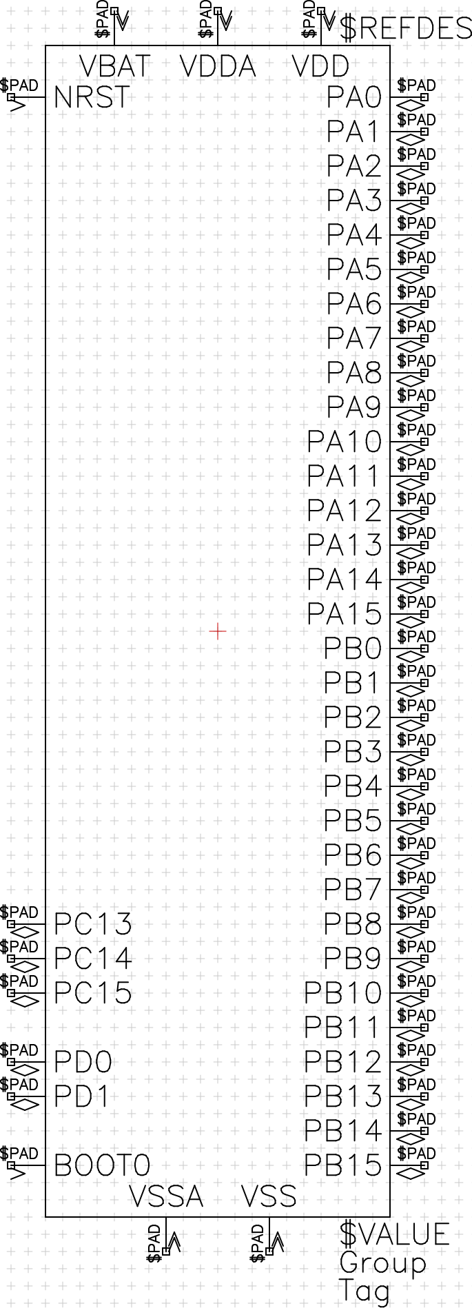
I extended the silkscreen clearance to both package outline and copper to 0.2 mm. Looks best when it's symmetric IMHO. I combined the power pins, but did not shift them to top and bottom of the symbol for a number of optical reasons:
Of course, all of this is personal preference and I don't have a problem with leaving this pull request open until there exists a clear convention on where supply pins should go in every case. |
|
Regarding the symbol: The only "guide" on how schematic symbols I've found so far is the kicad library convention which specifies power pins to be top/bottom: http://kicad-pcb.org/libraries/klc/S4.2/ Are you aware of any recognized standard documents covering this? The only ones I found so far deal with the basic stuff like diodes and capacitors but don't give any recommendations on how to draw nonstandard symbols. I'd like to avoid coming up with a new convention for the horizon pool if there are existing conventions to use. |
|
I didn't find anything apart from the KLC either. I think it would would be pretty hard to have a general convention which would look good and lead to neat schematics in every case. A convention is clearly needed, but I don't know if a rule anymore concrete than the KLC's “group similar pins together” is really beneficial because it will always look odd with some types of parts and thus lead to ambiguity. Maybe a more abstract, yet measurable rule like “The pin configuration, where the part's recommended configuration with all supporting passives needs the least space on the schematic” would be an option, too. A few days ago, I wanted to set up a library for simple pin headers and I noticed unsure I was without a convention. I'd prefer to set up a rough convention and refine it whenever some ambiguity is noticed, maybe with a poll on the different options. I could start a rough draft based on the KLC and IPC footprint rules in the next few days because that would help a lot in getting the process going. |
|
Don't get me wrong, I absolutely think that the established conventions are good in that they make mostly sensible decisions and because people are used to them, of course. But when designing a all-new library there's a huge potential of rethinking the design assumptions for the convention, because there are no legacy parts which have to somehow fit into the convention. I like to keep that in mind and rather discuss a bit longer on the convention than having to retro-fit some rules which turn out to be non-optimal. |
Go ahead! That's what I thought of in #8 as well. Having a clear convention in place makes it much easier for everyone to contribute parts to the pool. Having power/ground on top/bottom is the way I've always done it and seen it done in most places. Being able to rotate pin names shouldn't be that hard to implement, let's see.. |
|
Another way would be to almost always split the power pins into a separate unit. The only exception would be parts where the supply pins fulfill more of an analog purpose, like switching regulators or supply monitor ICs. In this particular case the controller would have two supply units for the digital and the analog supply. That would be nice, too, because you can put a inductor or ferrite bead or whatever you like neatly between them. |
|
IMO, splitting out the power supply pins doesn't make much sense for most devices with much less than 100 pins since it leads to more complex schematics. |
|
I rebased this PR since it wasn't able to merge without conflicts any more. |
|
This would be useful, is merging still an option @carrotIndustries ? Thanks :) |
|
Bot! |
|
This review has been superseded. Scroll down to find the latest one. |
|
|
Bot! |
|
This review has been superseded. Scroll down to find the latest one. |
I’ll add this to the convention as well (and to horizon-eda/horizon-pool-convention#7). Unless you have objections, I would also add a rule to prefer the ‘perpendicular’ name orientation unless this makes the symbol unreasonably wide. Fixed everything the bot complained about and redid the symbol. I don’t really know why the multiple symbol orientations popped up since I didn’t see the as set in the symbol editor. Let me know if you have additional comments! |
|
Bot! |
|
This review is brought to you by the Horizon EDA Poolbot commit bec8764. Items in this PR
Parts overview (excluding derived)Bold items are from this PR
Derived partsBold items are from this PR
Parts tableValues in italic are inherited
DetailsPartsSTM32F103C8T6TR✔️ Checks passed
STM32F103CBT6TRInerhits from STM32F103C8T6TR ✔️ Checks passed
EntitiesSTM32F103C✔️ Checks passed
UnitsSTM32F103C✔️ Checks passed
Symbol: STM32F103CIs expandable ✔️ Checks passed
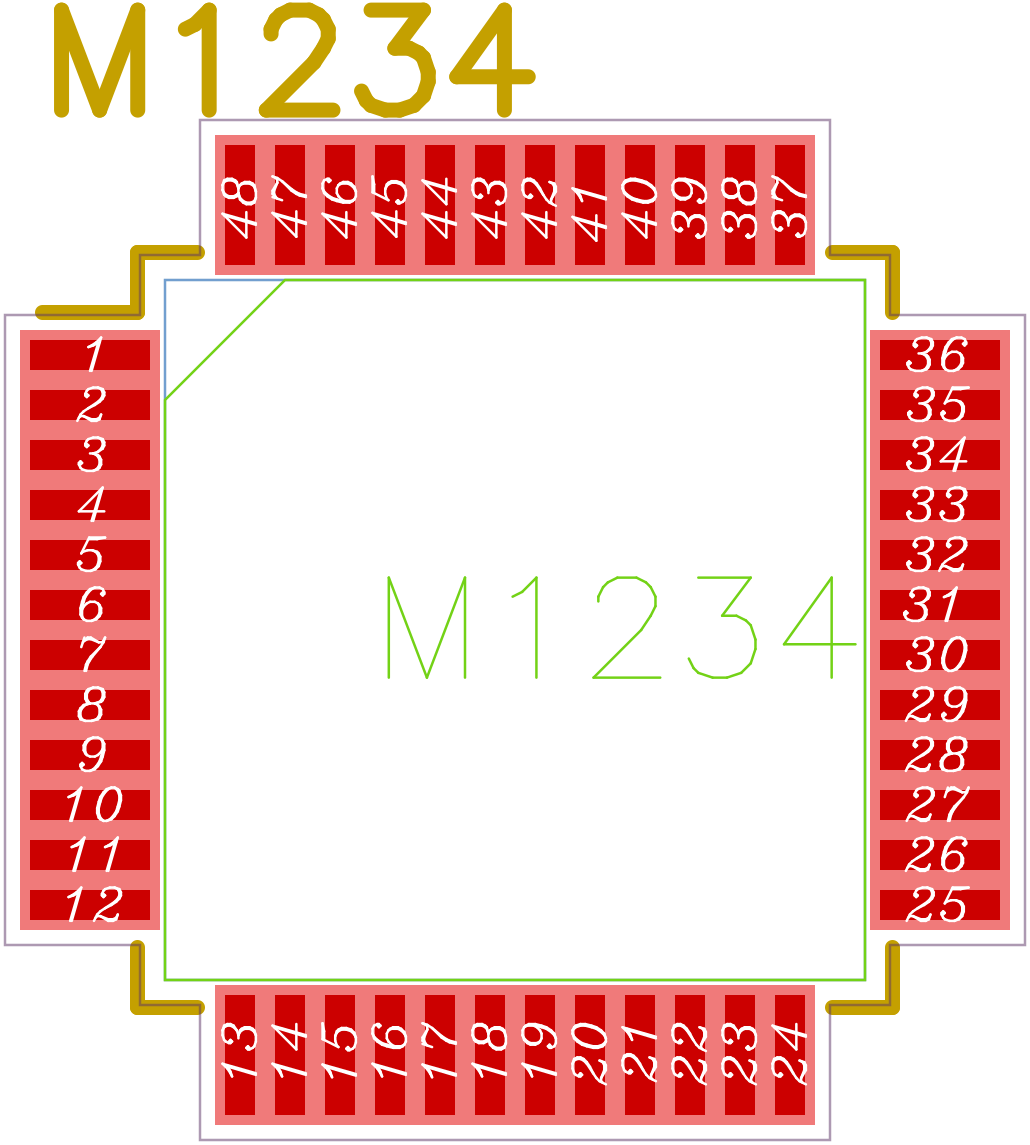
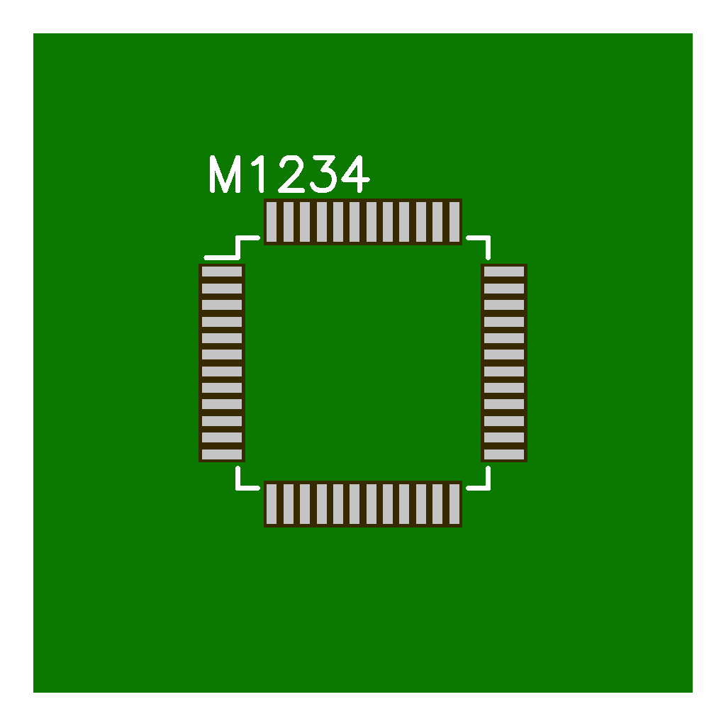
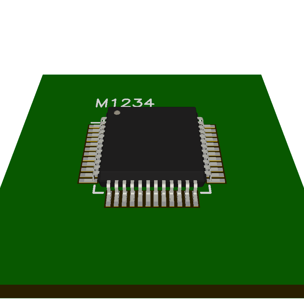
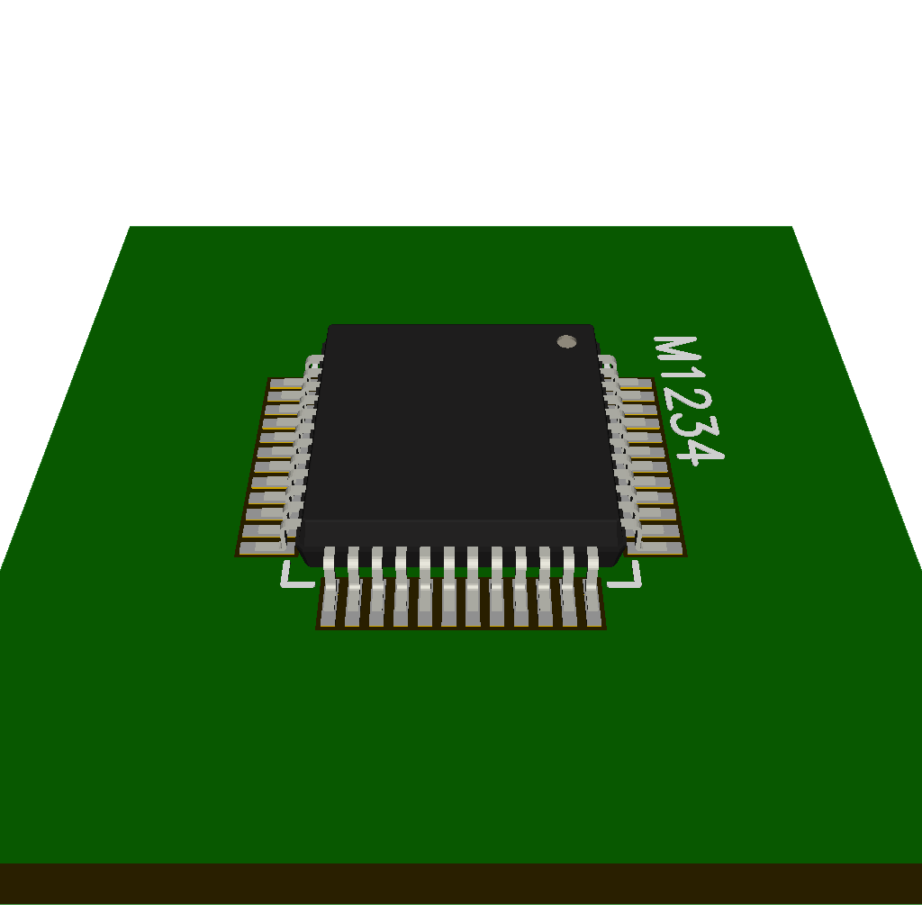
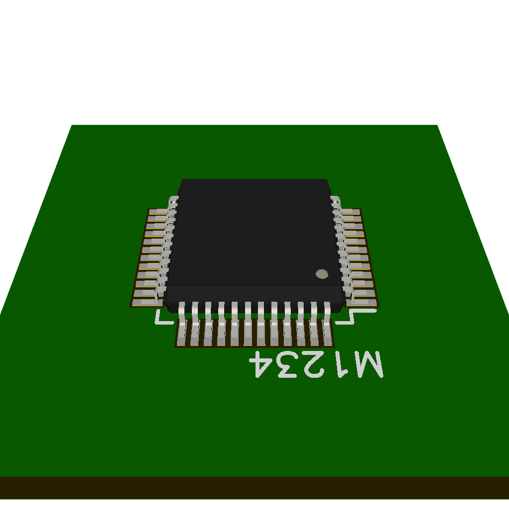
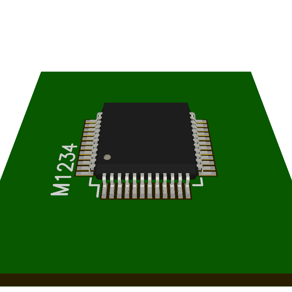
PackagesLQFP48
✔️ Package checks passed ✔️ Clearance checks passed
Parameters
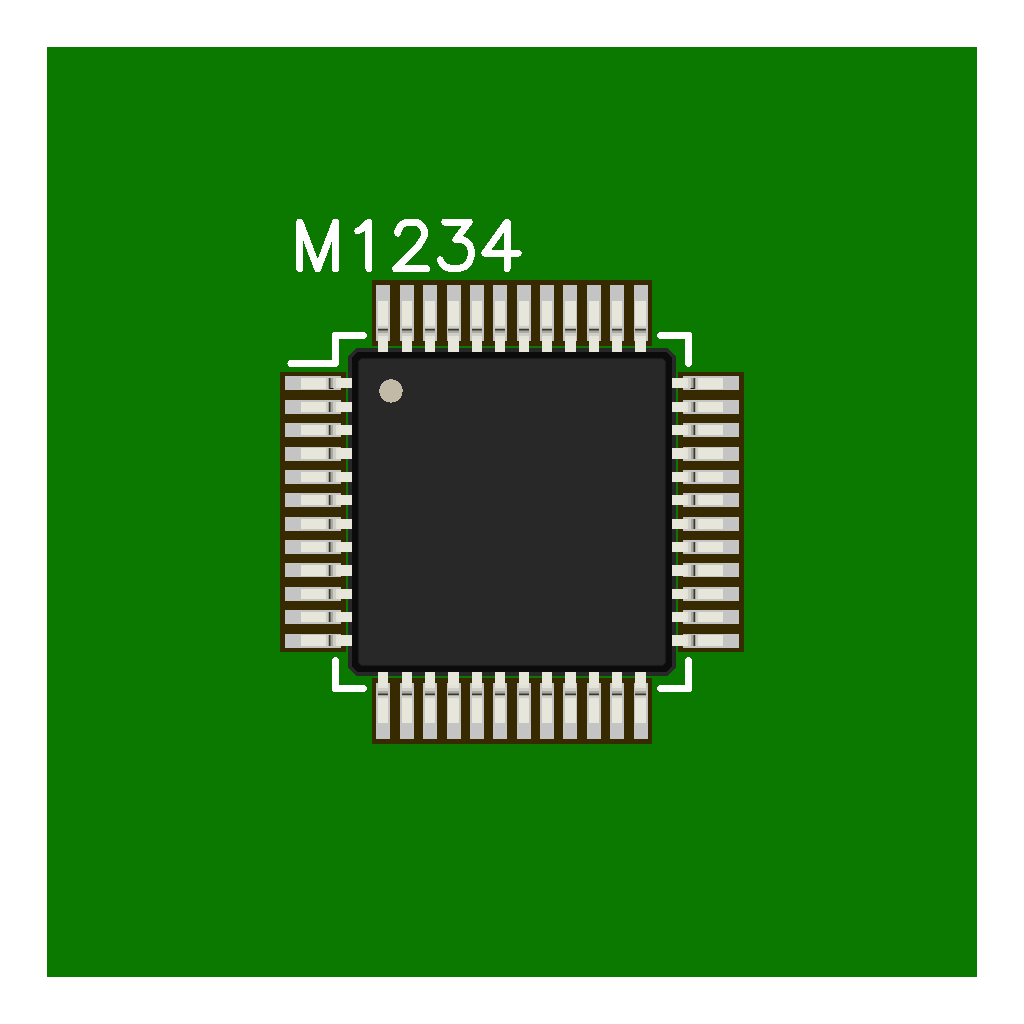
3D views (one model)Without model
LQFP-48_7x7mm_P0.5mm.step
Pitch analysis
|


No description provided.