The purpose of this project was to develop a hum-free electronic ceiling fan device that can be controlled remotely (IOT) or locally with a rotary encoder.
The selected processor was the ESP32-C3 in its mini development kit format.
As the purpose was to replace an old controller in my house, to fit it into a 100mm wall box I had to build a PCB to reduce footprint and use a 3D printer for the front cover that would fit a standard frame for electricity.
As in linux there is no support for fusion 360 use onshape to model the assembly and cads of the front cover which only requires a browser, and the result is amazing. And to design and manufacture the PCB use easyeda, the manufacturing service is good, but I could not export the pcba in step format, I had to use kicad.

To prevent humming, capacitive reactances are used to limit the current in the motor stator, and since the friction (blades etc) is moderately high, the rotation speed decreases. This version has four speeds to keep the form factor as small as possible, (capacitors and relays are large).
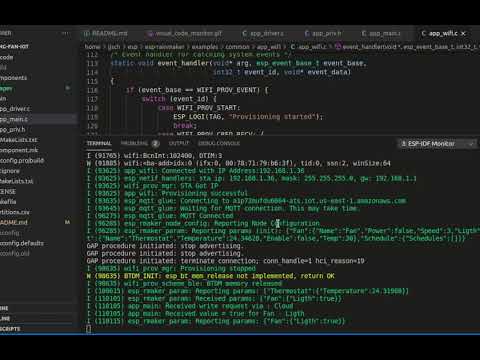
To control the device from a cell phone, Espressif Rainmaker is used, which has an application for android and iphone, which allows you to configure the Wi-Fi network (provisioning), and control the device through the AWS IOT.


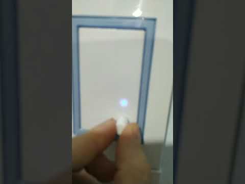
For local control, a pushbutton rotary encoder is used to set the speed and turn the fan light on/off. To improve the speed resolution, the user has to rotate the shaft three or more steps to increase/decrease.
Taking advantage of the fact that the ESP32-C3 mini board has a neopixel, the combinations of functions are indicated with colors and brightness levels. For example, when the light is off, the fan speed is indicated with 4 levels of brightness in red, but when it is on in green, and when the fan is off and the light on it turns blue to the maximum, and in idle the the led is white.
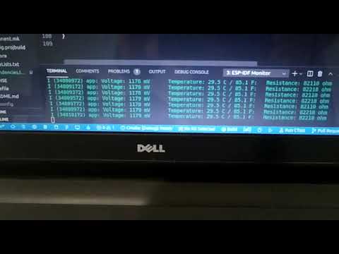
Controls the (ON / OFF) of the fan with temperature. As a sensor it uses a thermistor of 100K at 25 degrees Celsius with a beta of 4250 from Murata model NXRT15WF104FA1B040. The firmware uses the simplified Steinhart equation to linearize the response. The control implements a 2 degree hysterisis to improve system stability.

The MF52A104F3950 thermistor that I end up using in the final product is different than the one I used in the prototype, but the results are similar to what I got with the Murata, below is a video with the measurements. Click to play in Youtube
To power the electronic equipment, approximately 350 mA at 3.3V is required for the CPU when Wi-Fi is in active mode, and 90 mA at 5V for each relay. (350mA * 3.3V) = 1,155 W + (90 mA * 5 * 3 relays) = 1,350 W, total = 2,505 W. To increase the safety factor for the proof of concept select the Hi-Link source HLK-5M05 that delivers 5V at 1A which is twice the estimated power.

On page 7 of the datasheet, there is a table of suggestions for additional components such as a fuse to protect the circuit from damage when the module malfunctions, a capacitor for filtering and safety protection (EMC certified), and a filter / inductor in common. mode, for EMI filtering. And the last thing was adding a filter capacitor that can reduce the output ripple from the original 50mV to 30mV.
The next two images show the DC output and ripple output of the power supply without load.


The next two pictures show the DC output and ripple output of the power supply with the CPU running.


Press and hold the encoder button for more than 3 seconds to reset the board to factory defaults. You will have to provision the board again to use it.
The schematic of the ESP32-C3 version is simple, it consists of an output stage made up of 4 relays, an encoder for manual control, and a thermistor to control the thermostat. As a power supply it uses a 5V 600 mA HLK.

The first version of the prototype is a mix of Arduino boards with conventional electronics. The next version will add a power supply to test the concept on a fan.

The second version has the thermistor to control the fan thermostat.

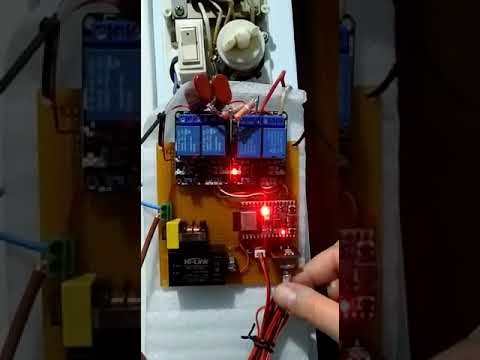
The third prototype is already functional and, although the form factor is not suitable for a wall mount, it allows to control the fan with all the specified functionalities. As you can see, it uses the ESP32-C3 version of the CPU.


The fourth prototype was to test a smaller relay that is essential for the equipment to fit in a 100mm box. Therefore, a test had to be performed with the new 932-5VDC-SL-AH 10A/0.45W relays to verify that they withstand current pulses when fan speeds change. NOTE: Sorry, but since the photo was taken after the final PCBA was assembled, it doesn't have the ESP32-C3 processor.

Below is a video of the test performed to evaluate the new relays. Click to play in Youtube.
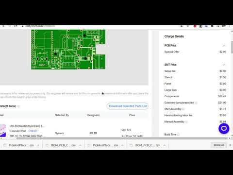
To design and manufacture the PCB I used the easyeda online service, which allows you to buy at least 5 units, in my case it works because I plan to replace 4 old fan controllers and I also wanted to experience what the import process is like in my country.


In this link you can access the project that is free under the MIT license, to reform it to your space needs, or if it works for you, you can order it directly from easyeda.
Images of the PCB mounted on the frame for the 100 mm deep-drawn box, typical of Argentina.


The following video shows the steps to be taken to order the boards with the assembled components except for the esp32-c3 processor, because for now they only mount one side of the PCB. Click to play in Youtube.
To mount the pcba in the commercial rack, design with onshape a cabinet front that with three screws allows mounting the board with a protector to avoid short circuits in metal boxes. In total, 3 pieces are required to be printed in petg: the front, the knob and the protector.

The application is written in C, based on Espressif IDF and as a development tool the Visual Code of MS was used with the Espressif plugin.
-
1 Download the IDF.
-
2 Download the Rainmaker.
-
3 Download the celing-fan-iot application code.
-
4 Select the device target CPU for ESP32-C3.

-
5 Build (compile and link).

-
6 Flash the code with visual code.

-
6.1 Flash the code with esptool
-
6.1.1 Download the bin files from bin folder.
-
6.1.2 Use esptool to update the CPU with the following command line.


python -m esptool --chip esp32c3 -b 460800 --before default_reset --after hard_reset write_flash --flash_mode dio --flash_size 4MB --flash_freq 80m 0x0 bin/bootloader.bin 0x8000 bin/partition-table.bin 0x16000 bin/ota_data_initial.bin 0x20000 bin/fan.bin
-
7 Run the serial monitor.

-
8 Download the Rain-Maker application for Android or iPhone.
-
9 Provisioning (Configure and connect to the Wi-Fi network) Click to play in Youtube.


- 10 Enjoy. Click to play in Youtube
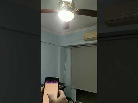
It shows how the ceiling fan can be controlled from the rainmaker cell phone APP that is connected to the AWS network. Click to play in Youtube.
It shows how the ceiling fan can be controlled manually. Click to play in Youtube.
For reference, this was the bulky externally mounted ceiling fan light speed controller.
