This project is designed to allow you to connect an Azure Sphere MT3620 based device to your Honeywell (Ademco) security panel and "listen in" for key events. This project is an implemenation of the reverse engineering of the Ademco ECP keypad bus devloped by Mark Kimsal, and modified by Morpheus (See credits at the bottom of this page).
The initial project scope was set to monitor the Panel and output the messages to an OLED display connected to the Sphere. The source code developed by Morpheus had to be translated to c in order for this to be used in an Azure Sphere high level App.
Then an Azure IoT Central App was developed and connectivity to it was implemented in this project. Find Template here
Finally, functionality to receive commands from the Azure IoT Central App and send them to the Panel was added. This step is still unstable. Some times the command does not reach the Panel. It may be due to the lack of tune up of the software serial tx implemented. A possible solution will be an RTC App to handle this task.
This project is developed using the following:
- Honeywell Vista 20P Security Panel Version 10.23 (the Panel).
- Azure Sphere MT3620 Starter Kit by Avnet with OLED Display (the Sphere).
- HiLetgo Mini RS232 to TTL (uses MAX3232).
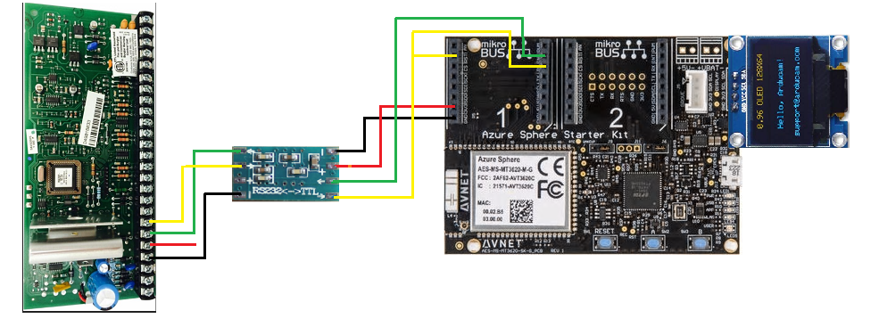
- Connect the Panel Terminal 7 (data-out wire, yellow) to a MAX3232 (R1IN) and the output (R1OUT) to pin GPIO28 (RX0, RX in Socket 1) on the Sphere. Alternatively, one can use GPIO33(RX1, MISO in Socket 1)
- Connect MAX3232 output (R1OUT) to pin (GPIO16) (RST in Socket 1) on the Sphere.
- Connect the Panel Terminal 6 (data-in wire, Green) to a MAX3232 (T1OUT) and the input (T1IN) to pin GPIO02 (INT in Socket 1) on the Sphere.
- Connect the Panel Terminal 4 (ground) wire, black) to a MAX3232 (-, in RS232 side)
- Connect the MAX3232 Ground (-, in TTL side) to GND on the Sphere.
- Connect the MAX3232 Vcc (+, in TTL side) to 3V3 on the Sphere.
If you are not familiar with setting up an Azure Sphere Stater Kit and how to connect an Azure High Level App with an Azure IoT Central App, review this Azure Sphere Starter Kit Advanced Tutorial
Once you understand these concepts, you can create an Azure IoT Central App using this Template. In the Azure IoT App you can create a new Device using the AzureSphere template device 1.1.0 and obtain the "Connection String" and "AllowedConnections" variable to be used in the connection_string.h and app_manifest.json files respectively.
Setup your hardware according to the wiring diagram above. Then build and run the AlarmKeyPad solution in the src folder.
Essentially, the data out wire uses 8-bit, even parity, 1 stop bit, inverted, NRZ +12 volt TTL signals. But, the data out wire also acts somewhat like a clock wire sometimes.
Regular messages are transmitted periodically and begin with either F7 or F2. F7 messages are fixed length, F2 are dynamic length. Both message types consist of a header and a body section. The second by of F2 messages indicate the remaining bytes for said message.
When behaving as a clock wire, the panel will pull the line high for an extended period of time (>10ms). Right after this a first group of 8 devices needing to send data should pusle a response. The Panel will read 9 bits the starting bit an a bit wich represents the address of each one of the 8 devices in the first group. Thrn another short high rise on the line will indicate the time for the second group to send data. Followed by another short high rise and then the time for the KeyPads group to send their pulse. For each device acknowledged by the Panel, an F6 message will be broadcast on the data out wire with the address of the device which should send data. F6 messages behave like normal serial data.
In order to avoid "open circuit" errors, every device periodically sends their device address to the panel. This happens after F7 messages, and as a response to input querying from the panel.
Pulsing doesn't exactly match up with serial data. Timing is handled by synchronizing to rising edges sent from the panel. After each one of the first two rises a delay equivalent to ten bits can be used before attempting to check for the next rise. After the third rise 9 bits of data can be send to the panel. A starting bit followed by address of the keypad as follows:
Address - 16    1 1000 0000
Address - 17    1 0100 0000
Address - 18    1 0010 0000
Address - 19    1 0001 0000
Address - 20    1 0000 1000
Address - 21    1 0000 0100
Address - 22    1 0000 0010
Address - 23    1 0000 0001
When multiple devices ack, their pulses should coincide. The result is that the last bit is ANDed together.
Address 16 - 1000 0000 Address 21 - 0000 0100 Together on the wire they look like a single byte of 1000 0100
(high)---\___(10ms low)___/---\______/---\_______/---\_____  (Yellow data-out)

__________________________/\_________/\__________/\_/\_____  (Green data-in)
This project uses some parts of Arduino IDE - specifically the SoftwareSerial library. So, whatever license that is under, this project is under (for the time being).
I could not have cracked the nut of Vista ECP protocol without knowing that it was possible by reading Miguel Sanchez's article in Circuit Cellar. Although he did not process signals sent from the panel, he figured out the baud rate, stop bit configuration, and the fact that the signal is inversed (0 is high, 1 is low).
Other projects that were invaluable to me are:
- Arduino SUMP analyzer firmware:
- Open Logic Sniffer (desktop):
- Original Code Mark Kimsal (homesecurity):
- Modified Code Morpheus (homesecurity):
