-
Notifications
You must be signed in to change notification settings - Fork 2
What delay lines teach about composition
Delay line-based effects, such as reverbs and echoes, provide several of useful lessons about challenging design decisions in a DSP system's architecture.
Block-based evaluation, without the ability to evaluate sections of a graph on a per-sample basis, creates a class hierarchy between the users of system-provided building blocks (i.e. unit generators, referred to here as "signals") and implementers of them. For example, in SuperCollider, it is very challenging (or impossible?) to build nested delay effects by composing unit generators together, since single-sample feedback loops can't be expressed in a purely block-based model. Such effects will require a user to leave the affordances of the SuperCollider environment behind and drop down to writing server plugins in C++ instead. When doing so, many of the opportunities for reuse are also taken away, and plugin authors often have to resort to reimplementing or cutting and pasting portion of the implementation of other unit generator plugins. Pure Data, on the other hand, allows users to define sub-patches where the block size and sample rate are customizable—-and these can be interconnected with patches running a different rates/block sizes.
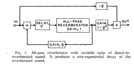
In the early 1960s, Manfred Schroeder developed a series of simple reverb topologies that are based on feedback and feedforward delay lines. The most interesting of these topologies, which ended up influencing the classic commercial reverbs of the 1970 and 80s, is Schroeder's second topology described in his 1962 paper, "Natural-Sounding Reverberation". This reverb consists of a chain of five allpass filters nested within a delay line that also has allpass characteristics:
In a DSP system, an all pass filter can be considered to be a fundamental component (i.e. a unit generator, or referred here to as a "signal") or encapsulated building block of signal processing. Such a signal would have three inputs:
- the source signal
- the delay time
- the feedback gain coefficient
The signal would then be responsible for encapsulating the basic delay line and filtering operations, including:
- reading from the delay line
- mixing the input with the scaled value read from the delay line, and writing it to the delay line
- mixing the value read from the delay line with the scaled input value, and outputting it
Signal Allpass {
    input source;
    input delayTime;
    input feedbackGain;
    output main;
    property DelayLine delay;

    generate() {
        float read = delay.read(delayTime);
        float toWrite = source + read * feedbackGain;
        delay.write(toWrite);
        main = read + toWrite * -feedbackGain;
    }
}
This works fine until a user wants to augment the behaviour of this all pass, for example to insert a series of other all pass filters inside the feedback loop. In this case, the inside of all pass "unit" has to be decomposed into a set of units that can be composed by a user:
Signal DelayReader {
    input delayTime;
    output main;
    property DelayLine delay;

    generate() {
        main = delay.read(delayTime);
    }
}

Signal DelayWriter {
    input source;
    property DelayLine delay;

    generate() {
        delay.write(source);
    }
}
With these discrete units in place, we can now compose them into a nested all pass reverb like the one suggested by Schroeder:
AudioIn input;
DelayReader reader;
Allpass ap1;
Allpass ap2;
Allpass ap3;
Allpass ap4;
Allpass ap5;
DelayWriter writer;

connect input to reader->source;
connect 0.03f to reader->delayTime;
connect reader to ap1->source;
connect ap1 to ap2->source;
connect ap2 to ap3->source;
connect ap3 to ap4->source;
connect ap4 to ap5->source;
connect ap5
toWrite = input + reader * 0.839f;
connect toWrite to writer->source;

return reader + toWrite * -feedbackGain;
