CT Sensor Amp Module
- 本基板はクランプ式CTセンサの出力を増幅してRMS値(実効値)に変換する基板です
- 交流電流に応じたRMS値(実効値)をアナログ値(直流)として得ることができます
- シャント抵抗、RMS値の演算ICを搭載しているため、交流電流の実効値をアナログ値として得ることが可能です
- 実効値をアナログ値として得られるため、マイコン側での高サンプリングAD変換やRMS演算等が不要です
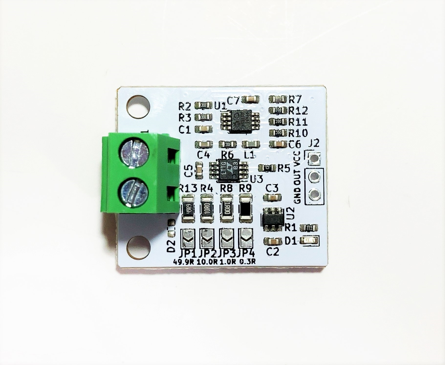
- CTセンサ入力アンプINA181A1アンプ、RMS換算LTC1966、低オフセット出力アンプMCP6V62を使用しています
- シャント抵抗は49.9Ω、10Ω、1Ω、0.3Ωの4種類から選択できます
- シャント抵抗、CTセンサによって異なりますが、最小0.1A~最大300A程度まで測定可能です(3.3V電源時)
- 基板サイズ25mm x30mm、固定穴M3x2 幅20mm
INA181A1によるゲイン20倍、出力段アンプゲイン3倍で合計60倍の増幅率です
VOUT= (I x Gain x R)/CT
I = (VOUT x CT)/(Gain x R)
VOUT:アナログ出力電圧(V)、I:CTセンサ対象電流(A)、Gain:60倍(固定)、R:シャント抵抗(Ω)、CT:巻き線比
例 VOUT=(IxGainxR)/(CT比)=(Ix60x49.9)/3000
- 1:3000のCTセンサを用いた場合の各シャント抵抗における最小電流と最大電流目安です
- 最大電流は増幅アンプ飽和の目安となる電圧から設定しています
- 最小電流はオフセット電圧が数10mV生じるため、影響を無視できる目安として設定しています
| シャント抵抗 | 最小電流A(電源3.3V) | 最大電流A(電源3.3V) | 最小電流A(電源5V) | 最大電流A(電源5V) |
|---|---|---|---|---|
| 49.9 | 0.1 | 3 | 0.1 | 5 |
| 10.0 | 0.5 | 15 | 0.5 | 23 |
| 1.0 | 5 | 150 | 5 | 230 |
| 0.3 | 10 | 340 | 10 | 500 |
- CTセンサは同梱されていません
- 巻き線比1:2000~3000前後ののCTセンサを使用してください
- 使用時は必ずシャント抵抗のいずれか1つをジャンパさせてください
- CTセンサの特性上、活線で2次側を解放すると数kVの電圧が発生しCTの損傷や感電の恐れがあります
- CTの損傷や感電を防ぐため、出力保護素子を内蔵したCTセンサの使用を推奨します
- 電源は3.3V、5Vに対応していますが、5V電源の方がレンジを確保できるため、より多くの電流を測定できます
- 電源電圧以上の出力はアンプが飽和するため、正しく出力されません
- AD変換の入力インピーダンスやオフセット電圧等の影響で、電流0Aでも数10mV程度の出力電圧が生じます
- 各シャント抵抗における最小電流以下の小さな電流測定には向きません
- 50Hz/60Hzの商用電源の電流をCTセンサで測定する用途を想定しています
- RMS演算ICによって真の実効値演算を得ていますが、大きな歪みやノイズが多い場合、正しく測定できない場合があります
- 回路上のローパスフィルタで高周波をカットオフしているため、数百Hz以上の電流変化は測定できません
- This board amplifies the output of a clamp-type CT sensor and converts it to an RMS value (effective value).
- The RMS value (effective value) according to the AC current can be obtained as an analog value (DC).
- Since it is equipped with a shunt resistor and an IC for calculating the RMS value, it is possible to obtain the effective value of the AC current as an analog value.
- Since the effective value can be obtained as an analog value, high sampling AD conversion and RMS calculation on the microcontroller side are not required.
- It uses a CT sensor input amplifier INA181A1 amplifier, an RMS conversion LTC1966, and a low offset output amplifier MCP6V62.
- You can choose from four types of shunt resistors: 49.9Ω, 10Ω, 1Ω, and 0.3Ω.
- Although it depends on the shunt resistor and CT sensor, it can measure from a minimum of 0.1A to a maximum of about 300A (when using a 3.3V power supply).
- Board size 25mm x 30mm, fixing hole M3x2 Width 20mm
The INA181A1 has a gain of 20x, and the output stage amplifier has a gain of 3x, giving a total amplification rate of 60x.
VOUT= (I x Gain x R)/CT
I = (VOUT x CT)/(Gain x R)
VOUT: Analog output voltage (V), I: CT sensor target current (A), Gain: 60x (fixed), R: Shunt resistance (Ω), CT: Winding ratio
ex) VOUT=(IxGainxR)/(CT ratio)=(Ix60x49.9)/3000
- Minimum and maximum current guideline for each shunt resistance when using a 1:3000 CT sensor
- Maximum current is set based on the voltage that is the guideline for amplifier saturation
- Minimum current is set as a guideline where the effect of offset voltage of several tens of mV can be ignored
| Shunt resistance | Minimum current A (power supply 3.3V) | Maximum current A (power supply 3.3V) | Minimum current A (power supply 5V) | Maximum current A (power supply 5V) |
|---|---|---|---|---|
| 49.9 | 0.1 | 3 | 0.1 | 5 |
| 10.0 | 0.5 | 15 | 0.5 | 23 |
| 1.0 | 5 | 150 | 5 | 230 |
| 0.3 | 10 | 340 | 10 | 500 |
- CT sensor is not included.
- Use a CT sensor with a winding ratio of approximately 1:2000~3000.
- When using, be sure to jumper one of the shunt resistors.
- Due to the characteristics of the CT sensor, if the secondary side is released with a live line, a voltage of several kV will be generated, which may damage the CT or cause electric shock.
- To prevent damage to the CT or electric shock, we recommend using a CT sensor with a built-in output protection element.
- The power supply supports 3.3V and 5V, but a 5V power supply provides a larger range, allowing you to measure more current.
- Outputs above the power supply voltage will not be output correctly because the amplifier will saturate.
- Due to the effects of the input impedance of the AD conversion and offset voltage, an output voltage of several tens of mV will be generated even at a current of 0A.
- Not suitable for measuring small currents below the minimum current of each shunt resistor.
- Intended for use in measuring the current of a 50Hz/60Hz commercial power supply with a CT sensor.
- True RMS values are calculated using an RMS calculation IC, but if there is a lot of distortion or noise, measurements may not be taken correctly. * Current changes above a few hundred Hz cannot be measured because the low-pass filter in the circuit cuts off high frequencies.