-
Notifications
You must be signed in to change notification settings - Fork 9
Simulation
There are multiple simulations program available such as Gazebo, VREP, Webot (there are models of NASA mars rover there too), or even game engine. Here I will talk about how to build a simulation to run on Gazebo that runs with ROS control (cause ROS generally uses Gazebo simulation). To understand the simulation files and how they work, you should know about TF, URDF, and ROS control. Going through their tutorial will help significantly. I will also mention how to properly convert the SolidWorks file to STL file with the correct coordinate.
For Software Team:
- Know TF, URDF, and ROS Control
For Mech Team:
- Know how to convert Solidworks file (or whatever CAD program you use) into STL file. All we need is that mesh file, but you have to set the origin coordinate of that mesh file correctly so it makes software life easier. Going through TF and URDF will give you more ideas. Also know robotics kinematics and transformation really well would help.
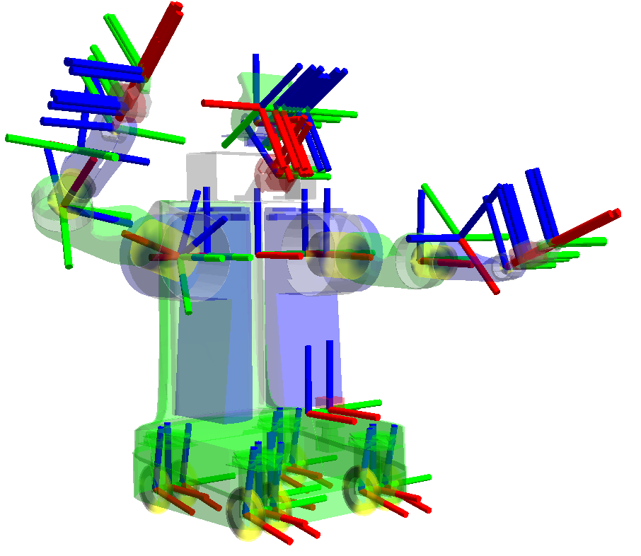
- This ROS library pretty much does all the forward and inverse kinematic for you. This will help you understand how the link and joint works as well as where they are when you create a URDF file. Also good for debugging.
- The library can help you transform from Row Pitch Yaw (RPY) to Quaternion and vice versa
- Note that in URDF, it use RPY format to form link and joint from parent link to child link
URDF (Universal Robot Description Format) is an XML code that specifies the links, joints, looks, etc. of robot (as well as transmission which tell which joint are controllable in ros control)
Xacro is just something like URDF, but it allows more programming capability (like make function, or import file). Here I won't be talking much about xacro cause it's just like urdf. Once you understand URDF, xacro just help organize the file so it's totally recommend you learn that too. Xacro
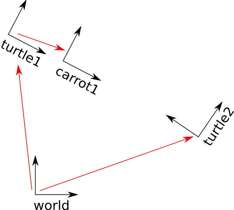
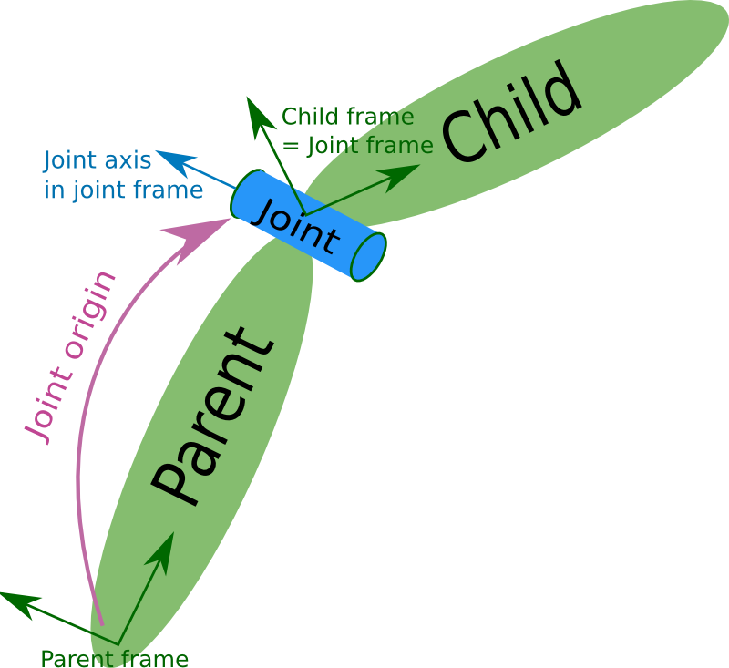
Just like TF, URDF specify a relationship between joint and link
For giving name to robot
<robot name="rrbot" xmlns:xacro="http://www.ros.org/wiki/xacro">
If want robot to be fixed to world. Create a link that have joint between it and the world
<link name="world"/>

<joint name="fixed" type="fixed">
 <parent link="world"/>
 <child link="link1"/>
</joint>
Else for other links
<!-- Base Link -->
<link name="link1">
<collision>
  <origin xyz="0 0 ${height1/2}" rpy="0 0 0"/>
  <geometry>
    <box size="${width} ${width} ${height1}"/>
  </geometry>
</collision>

<visual>
  <origin xyz="0 0 ${height1/2}" rpy="0 0 0"/>
  <geometry>
    <box size="${width} ${width} ${height1}"/>
  </geometry>
  <material name="orange"/>
</visual>

<inertial>
  <origin xyz="0 0 1" rpy="0 0 0"/>
  <mass value="1"/>
  <inertia
    ixx="1.0" ixy="0.0" ixz="0.0"
    iyy="1.0" iyz="0.0"
    izz="1.0"/>
</inertial>
You can check all the available tags on URDF page. Collision tell how it will collide. Visual tell how it should look like which is showed in Gazebo. Usually visual will be the mesh file. The collision could be mesh file, but if file is big or you want to optimize the simulation (cause collision of mesh will take some computation) some people just use simple shapes like boxes or cylinder as collision.
<joint name="joint2" type="continuous">
 <parent link="link2"/>
 <child link="link3"/>
  <origin xyz="0 ${width} ${height2 - axel_offset*2}" rpy="0 0 0"/>
  <axis xyz="0 1 0"/>
 <dynamics damping="0.7"/>
</joint>
Usually just need parent, child, origin, and axis
For those mechanical, you may want to see URDF part to get the idea of how the link and joint works. Pretty much the origin of the STL file will be the starting point and the software have to match the joints and links of all of them. Therefore, it's best to make the origin of that STL the axis of rotation / joint of that part.
- when saving as STL, click option
- checking “Do not translate STL output data to positive space” will make it use the origin coordinate of Solidworks
- or just choose output coordinate system at the bottom (if you made one) so this way you can design the part using any coordinate system and create the one you want to use for STL
- To check if coordinate is right, just open the STL file with Solidworks, and see where origin is
Now to create ros control, there are 2 ways
- Just use Moveit Setup Assistant and follow their tutorial
- Do it yourself, which I'm going to cover here
First, to allow ros control for both real and simulate robot, add a transmission tag to your URDF file
  <transmission name="tran1">
    <type>transmission_interface/SimpleTransmission</type>
    <joint name="joint1">
     <hardwareInterface>EffortJointInterface</hardwareInterface>
    </joint>
    <actuator name="motor1">
     <hardwareInterface>EffortJointInterface</hardwareInterface>
     <mechanicalReduction>1</mechanicalReduction>
   </actuator>
 </transmission>
If you are dealing with real robot, change the EffortJointInterface in hardwareInterface tag to hardware_interface/EffortJointInterface. Transmission Note that you can change EffortJointInterface to whatever controller you want such as VelocityJointInterface if you want to control joint velocity. See available controller here
Also if you are doing this in Gazebo, add the gazebo ros control plugin as well. Don't forget to download it through apt-get install if you don't have it.
<gazebo>
 <plugin name="gazebo_ros_control" filename="libgazebo_ros_control.so">
  <robotNamespace>/YourRobotName</robotNamespace>
 </plugin>
</gazebo>
Now we need to create a .yaml file. Put this in a config folder. Just look here to see how your files should be structured. The yaml file has the parameter that specify the type of controller, joints it's controlling, and other tuning parameters like PID. The file looks like this:
rrbot:
 # Publish all joint states -----------------------------------
 joint_state_controller:
   type: joint_state_controller/JointStateController
   publish_rate: 50

 # Position Controllers ---------------------------------------
 joint1_position_controller:
   type: effort_controllers/JointPositionController
   joint: joint1
   pid: {p: 100.0, i: 0.01, d: 10.0}
 joint2_position_controller:
   type: effort_controllers/JointPositionController
   joint: joint2
   pid: {p: 100.0, i: 0.01, d: 10.0}
What you see there is the robot name of rrbot corresponding to robot name in urdf file, the joint state controller that publish all joint state (so other controller can use and it will help you debug), and 2 position controller for joint11 and joint2 (make sure those joints have transmission tag in urdf) Note that there's a ros rqt that let you try tuning the paremeter while robot is running (I think). Else you could just try tuning it yourself.
Now you can create a launch file that run all those controllers. This is what it'll look like
<launch>

  <!-- Load joint controller configurations from YAML file to parameter server -->
  <rosparam file="$(find rrbot_control)/config/rrbot_control.yaml" command="load"/>

  <!-- load the controllers -->
  <node name="controller_spawner" pkg="controller_manager" type="spawner" respawn="false"
    output="screen" ns="/rrbot" args="joint1_position_controller joint2_position_controller joint_state_controller"/>

  <!-- convert joint states to TF transforms for rviz, etc -->
  <node name="robot_state_publisher" pkg="robot_state_publisher" type="robot_state_publisher"
    respawn="false" output="screen">
    <remap from="/joint_states" to="/rrbot/joint_states" />
  </node>

</launch>
in the argument, pass the argument as all the names of the controllers in the yaml file. Now you can run the simulation and the file. Note that you can control those joint that has controller by publishing through its topic (which should end with name cmd I think, but that's for most case). Some controller though (such as trajectory controller) may be control through ros service.
A few thing to note about Gazebo is that you can command it through rosservice (which is request and response action). Just try rosservice list and you can see so many option such as resetting the world.
Wondering how to make nice formatting? Check out this guide!


