-
Notifications
You must be signed in to change notification settings - Fork 9
Simulation
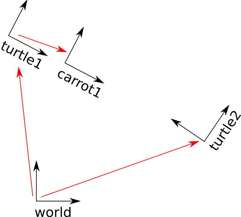
There are multiple simulations program available such as Gazebo, VREP, Webot (there are models of NASA mars rover there too), or even game engine. Here I will talk about how to build a simulation to run on Gazebo that runs with ROS control (cause ROS generally uses Gazebo simulation). To understand the simulation files and how they work, you should know about TF, URDF, and ROS control. Going through their tutorial will help significantly. I will also mention how to properly convert the SolidWorks file to STL file with the correct coordinate.
For Software Team:
- Know TF, URDF, and ROS Control
For Mech Team:
- Know how to convert Solidworks file (or whatever CAD program you use) into STL file. All we need is that mesh file, but you have to set the origin coordinate of that mesh file correctly so it makes software life easier. Going through TF and URDF will give you more ideas. Also know robotics kinematics and transformation really well would help.
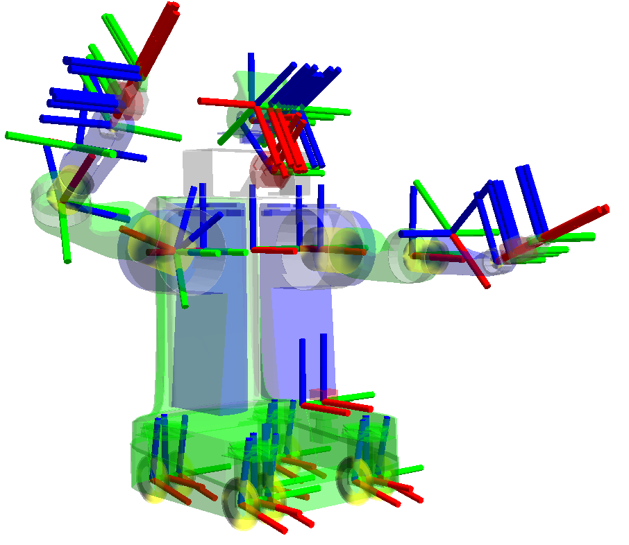
- This ROS library pretty much does all the forward and inverse kinematic for you. This will help you understand how the link and joint works as well as where they are when you create a URDF file. Also good for debugging.
- The library can help you transform from Row Pitch Yaw (RPY) to Quaternion and vice versa
- Note that in URDF, it use RPY format to form link and joint from parent link to child link
URDF (Universal Robot Description Format) is an XML code that specifies the links, joints, looks, etc. of robot (as well as transmission which tell which joint are controllable in ros control)
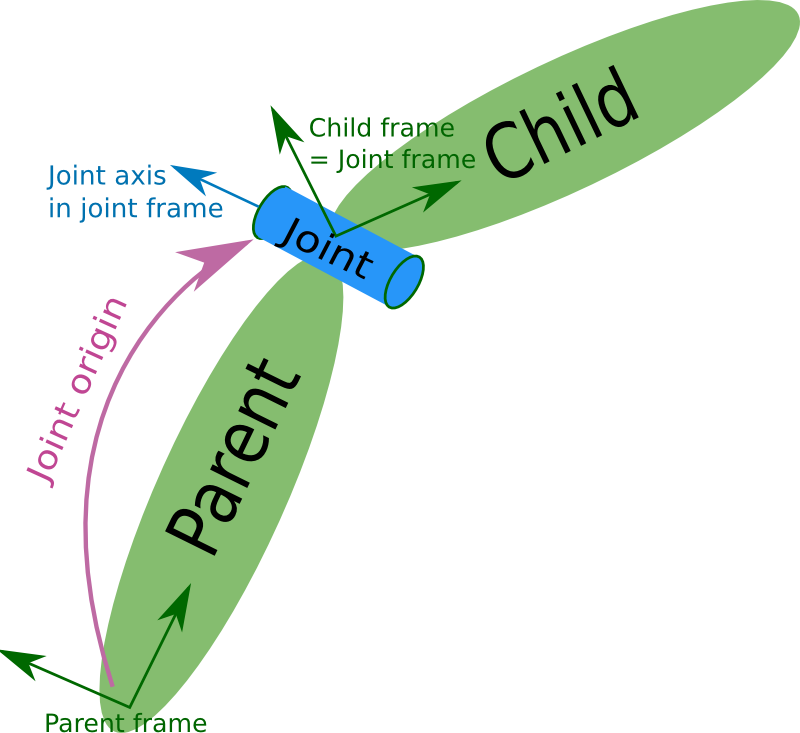
Just like TF, URDF specify a relationship between joint and link
For giving name to robot
<robot name="rrbot" xmlns:xacro="http://www.ros.org/wiki/xacro">
If want robot to be fixed to world. Create a link that have joint between it and the world `
`Else for other links
`
<visual>
  <origin xyz="0 0 ${height1/2}" rpy="0 0 0"/>
  <geometry>
    <box size="${width} ${width} ${height1}"/>
  </geometry>
  <material name="orange"/>
</visual>

<inertial>
  <origin xyz="0 0 1" rpy="0 0 0"/>
  <mass value="1"/>
  <inertia
    ixx="1.0" ixy="0.0" ixz="0.0"
    iyy="1.0" iyz="0.0"
    izz="1.0"/>
</inertial>
You can check all the available tags on URDF page. Collision tell how it will collide. Visual tell how it should look like which is showed in Gazebo. Usually visual will be the mesh file. The collision could be mesh file, but if file is big or you want to optimize the simulation (cause collision of mesh will take some computation) some people just use simple shapes like boxes or cylinder as collision.
<joint name="joint2" type="continuous">
<parent link="link2"/>
<child link="link3"/>
<origin xyz="0 ${width} ${height2 - axel_offset*2}" rpy="0 0 0"/>
<axis xyz="0 1 0"/>
<dynamics damping="0.7"/>
</joint>``
Usually just need parent, child, origin, and axis
### Exporting Solidworks to STL

* when saving as STL, click option
* checking “Do not translate STL output data to positive space” will make it use the origin coordinate of Solidworks
* or just choose output coordinate system at the bottom (if you made one)
so this way you can design the part using any coordinate system and create the one you want to use for STL
* To check if coordinate is right, just open the STL file with Solidworks, and see where origin is
## Rover Simulation
## Arm Simulation
Wondering how to make nice formatting? Check out this guide!


