Disassembly Tool Window
The Disassembly tool window (ZX Spectrum IDE|Z80 Disassembly) is one of the most versatile windows in the development environment. You can use it for many purposes:
- Examine the ZX Spectrum ROM
- Analyze the memory map and the code of an app written in Z80 assembly
- Add your annotations to the ROM
- Add your annotations to the application code
- Follow the code as you debug an app
The Disassembly tool, as its name suggests, displays the disassembly of the ZX Spectrum memory. Besides the list of Z80 instruction, it has a command prompt and a ROM annotation switch.
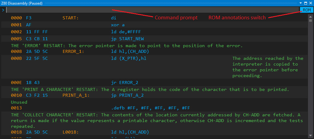
As the screenshot indicates, the disassembly window displays annotations (prefix comments, suffix comments, labels, and literals). A ZX Spectrum Code Discovery project adds a ROM file with predefined custom annotations. Nonetheless, you can add your custom annotations to the ROM, and those are automatically saved with the project.
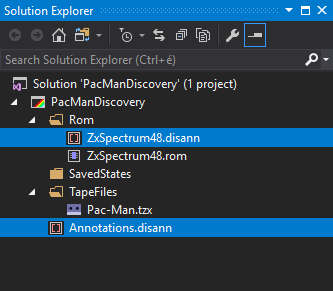
Annotations can be saved either to the ROM annotation file (ZxSpectrum48.disann in the figure beneath)
or the custom annotation file (Annotations.disann). The ROM annotations switch influences where
the annotations that belong to the ROM address space are saved. In ROM mode turned on
(the blue background indicates this mode), the ROM annotation file stores them; otherwise,
the custom annotations file keeps them.
You can click on the ROM annotation switch to turn it on or off.
Note: Any annotation that is out of the ROM address space (#0000-#3FFF) goes into the custom annotation file. Though right now the project handles only a single custom annotation files, in the future you will be able to use multiple annotation files.
Besides comments, labels, and literals, the annotations store the memory map. The Disassembly view utilizes this map to decide how certain parts of the memory should be displayed to the user working on a particular project. The great thing is that you can dynamically change the memory map, and the current settings are stored with your project.
The memory map is a list of memory segments, each of them with a 16-bit start and end memory address, and one of the following display types:
- Disassembly: The segment is displayed as a series of Z80 assembly operations
-
Bytes: A series of bytes as the arguments of the
.defbpragma -
Words: A series of 16-bit words (
.defwpragma) -
"Skip" section: A
.skippragma that marks a segment out of interest. -
Calculator section: A series of Spectrum 48K
RST #28floating point calculator bytecodes.
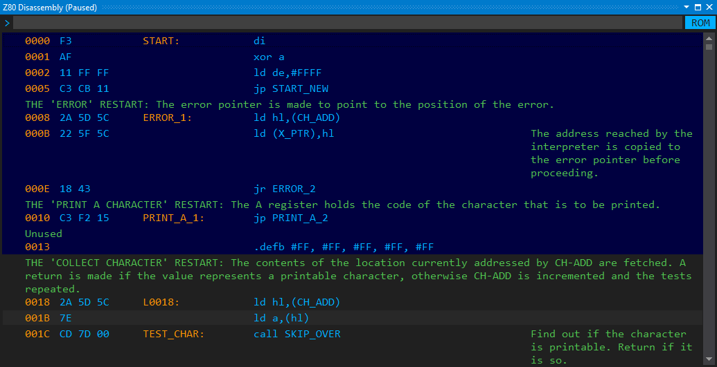
The following figures demonstrate these segment types. Here, the section starting at 0013
is a Bytes (.defb) section, while the preceding one (0000-0012) is a disassembly section:
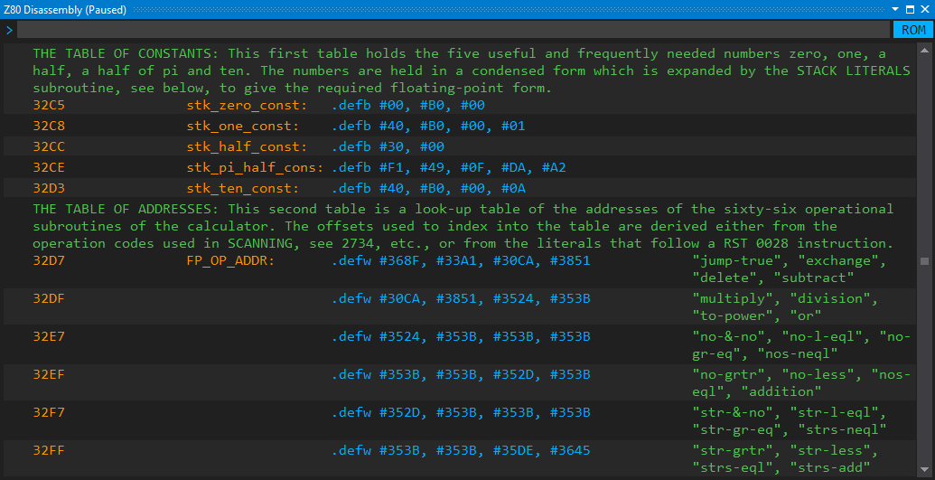
Take a look at the ROM's calculator tables that use word (.defw) and byte (.defb) sections:
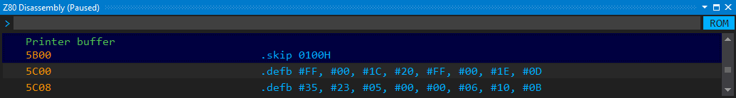
This sample shows how the content of the Printer buffer area (5B00-5BFF)
is marked as a .skip section:
Note: I plan to add other section types to the memory map in the future, for example, BASIC section, VARIABLES section, and STACK section.
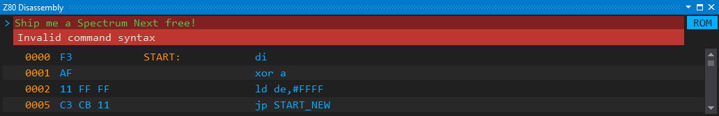
You can type simple commands in the command prompt, and execute them by pressing the Enter key. The commands are case insensitive. Whenever you type something that the disassembly view does not understand, you will recognize it from the dark-red-shaded command prompt background:
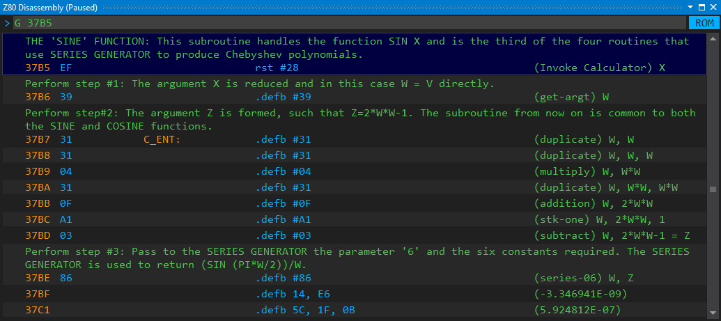
You can jump to a particular address with the G (Go to) command that accepts a
hexadecimal address, like G 375B:
Note: When you specify an address in the middle of a Z80 instruction, or in another section, the view shows the subsequent line.
Besides the Go to command, you can use these keys for the navigation, too: Up, Down, Page Up, Page Down, Ctrl+Page Up, Ctrl+Page Down, Home, End. They behave as you expect them.
You can dynamically change the current memory map with the following commands:
-
MD: Disassembly section -
MB: Byte section -
MW: Word section -
MS: Skip section -
MC: Calculator section
The commands accept two mandatory hexadecimal addresses; these are used as the start and end address of the section. Both addresses are inclusive.
When you add a new section, the memory is mapped again; the IDE automatically resolves collisions with the previously defined sections: the newly created sections always overwrite the older ones.
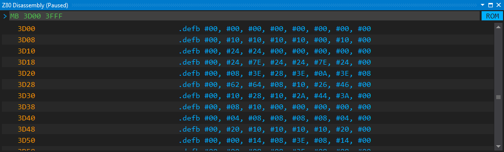
The 3D00-3FFF section of the ROM holds the character set. Let's assume it is assigned to a disassembly section:
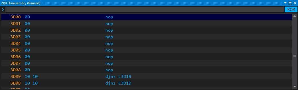
Let's represent them as a series of bytes with this command:
MB 3D00 3FFF
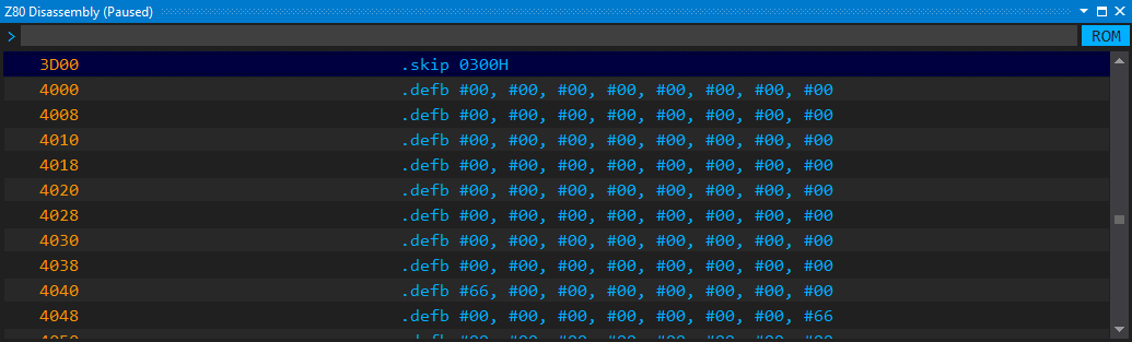
Well, you could use this command to represent the character set as a .skip
section:
MS 3D00 3FFF
Sometimes, you need to display a series of bytes as a set of Z80 instructions. For example, the Pac-Man game puts some loader code into the printer buffer area (5B00-5BFF). Let's display the code hiding here!
MD 5B00 5BFF
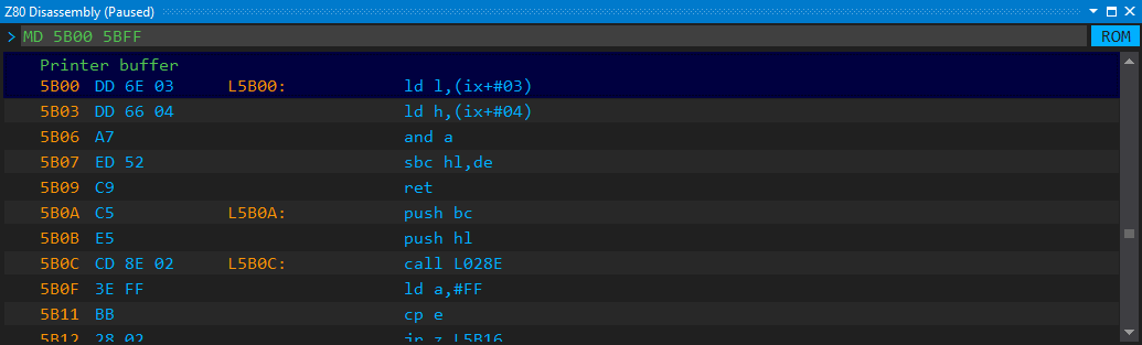
Note: The IDE automatically merges multiple adjacent disassembly sections into a single one, but it does not do the same with other sections.
Using self-explaining label names instead of automatic ones (such as L12AF) would help
you understand the code better. The Disassembly view supports a few comments that allow
naming and renaming labels. The L command accepts a hexadecimal address (label address)
and an optional name. When you specify the name, that will be assigned to the address as its label.
If you specify only the address, the IDE removes the label name from the address.
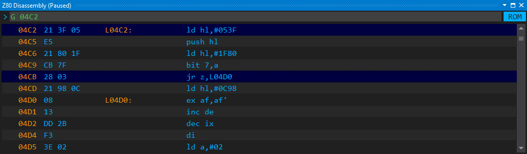
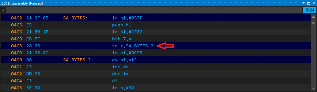
Let's see an example! Use the G 04C2 command to navigate to the 4C2 address of the ROM.
This is the entry point of the cassette handling routines, namely the SA_BYTES subroutine.
As you can observe, the 4CB address is a jump instruction to the 4D0 address.
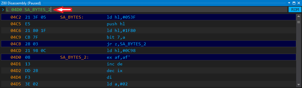
Execute these commands after each other to give names to the labels:
L 04C2 SA_BYTES
L 04D0 SA_BYTES_2
The disassembly view immediately shows the labels, and as you can see in the 4CB jump instruction, the reference to the label is also updated with the custom name.
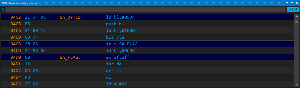
I guess, the SA_BYTES_2 is not a good name. The Complete Spectrum ROM
Disassembly Guide names it SA_FLAG. You can easily change the name with the
L 04D0 SA_FLAG command.
There is another way. You can use the RL 04D0 (Retrieve Label) command that
not only reads the label's name but prepares the L 04D0 SA_BYTES_2 command line
so that you can modify and re-enter it:
Fix the name (change it to SA_FLAG) and press Enter. The disassembly view gets immediately updated.
Note: Labels must start with a letter or underscore (_), and may contain only letters and numbers, or the underscore character. Their maximum length is 16 characters.
If something adds extra value to a disassembly list, a comment does. The IDE allows you to add both prefix comments (displayed above the Z80 instruction line) and suffix comments (shown to the right of a disassembly line).
They follow the very same logic as labels. With the P command,
you can assign a prefix comment to a line. Pass its hexadecimal address and the
comment text. The C command works similarly, nonetheless, it creates a suffix
comment.
You can use the RP and RC commands to retrieve suffix and prefix comments
for editing, respectively. Just as the RL command does, they prepare a
command line for modification and re-entry.
Take a look at the line 0095 in this screenshot:
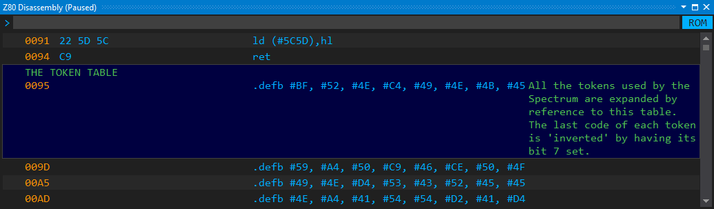
I added the adornments of this line with these commands:
P 0095 THE TOKEN TABLE
C 0095 All the tokens used by the Spectrum are ...
(Of course, I deliberately removed the long tail of the suffix comment.)
You can assign literals to values in the disassembly, similarly as you can associate labels with addresses. However, literals are a bit different. While a label is a one-to-one association between a name and an address, one or more literals can be associated with the very same value. Of course, a literal may have a single value.
To be clear, here are a few Z80 disassembly instructions with values that can be associated with literals:
ld hl,#0205   ; --> #0205
add a,#AC     ; --> #AC
ld (#4000),bc ; --> #4000
These instructions can be displayed in the disassembly this way, provided
we set up the KEY_TABLE_L, AC_VAL, and SMEM_START literals with
their proper value:
ld hl,KEY_TABLE_L
add a,AC_VAL
ld (SMEM_START),bc
The disassembly view provides the D command to let you add literals
to other annotations. You can use these forms of the command:
D [address] [literal name]
D [address]
D [address] #
These commands use the disassembly line with a Z80 instruction that
starts at the specified [address]. If that very instruction has a
value, that value is associated with a [literal name]. The #
argument says that the value of the instruction should be associated
with a literal that the same value as the one held by the instruction.
Fix it: 0058 --> 0074, #5C5D
Let's see these commands in action! Use the G 0074 command to scroll
to the CH_ADD_P1 subroutine, as this figure shows:
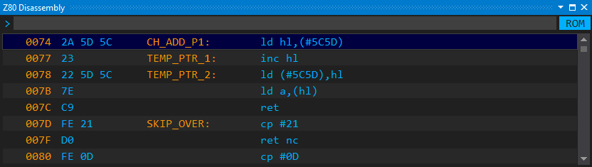
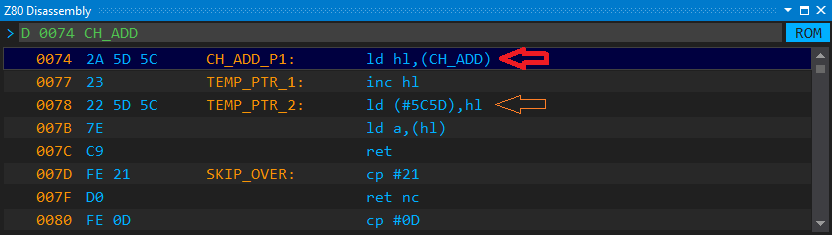
The instruction at 0074, namely ld hl,(#5C5D) utilizes the CH_ADD
system variable. To show this name instead of the hexadecimal value,
type the D 0074 CH_ADD command! It defines the literal CH_ADD for
the value 5C5D, and immediately replaces the value in the disassembly output:
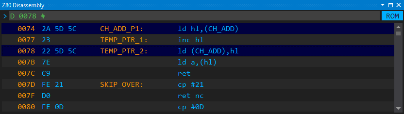
Now take a look at the instruction at 0078! That one uses the 5C5D value, too. The disassembler did not associate that value automatically with CH_ADD. It cannot be entirely sure that the hexadecimal value at the second instruction has the same semantic meaning, and thus can use the same literal, as the first instruction at 0074.
You have to manually resolve this reference. You do not have to remember the
name of the symbol that covers 5C5D. Enter the D 0078 # command,
and the disassembler will automatically infer that association:
With the command prompt in the disassembly view, you can manage breakpoints, too. These are the commands you can use:
-
SB [address]: Set a breakpoint at the specified address -
TB [address]: Toggle a breakpoint -
RB [address]: Remove a breakpoint -
EB: Erase all breakpoints
You can find more information about breakpoints in the Debugging section.