Chapter 3
Let's make gears and bearings!
Blender uses Materials to define the render appearance of Objects. Using Materials can be as simple or as complex as necessary to achieve the desired effect.
In this chapter, I will explain:
- Installing Blender Addons
- Creating simple Materials
- Scene Lighting via Sky Textures and HDRIs
Materials are powerful systems for defining how an Object appears during render. Blender's lighting simulation interacts with the Material of an Objects in the Scene in order to simulate the appearance of things like reflection, translucence, refraction, and so on. The power of Materials comes from their extensive customizability and potential for re-use; they can be used to generate the appearance of just about any substance imaginable, and once defined they can be reused wherever the user sees fit.
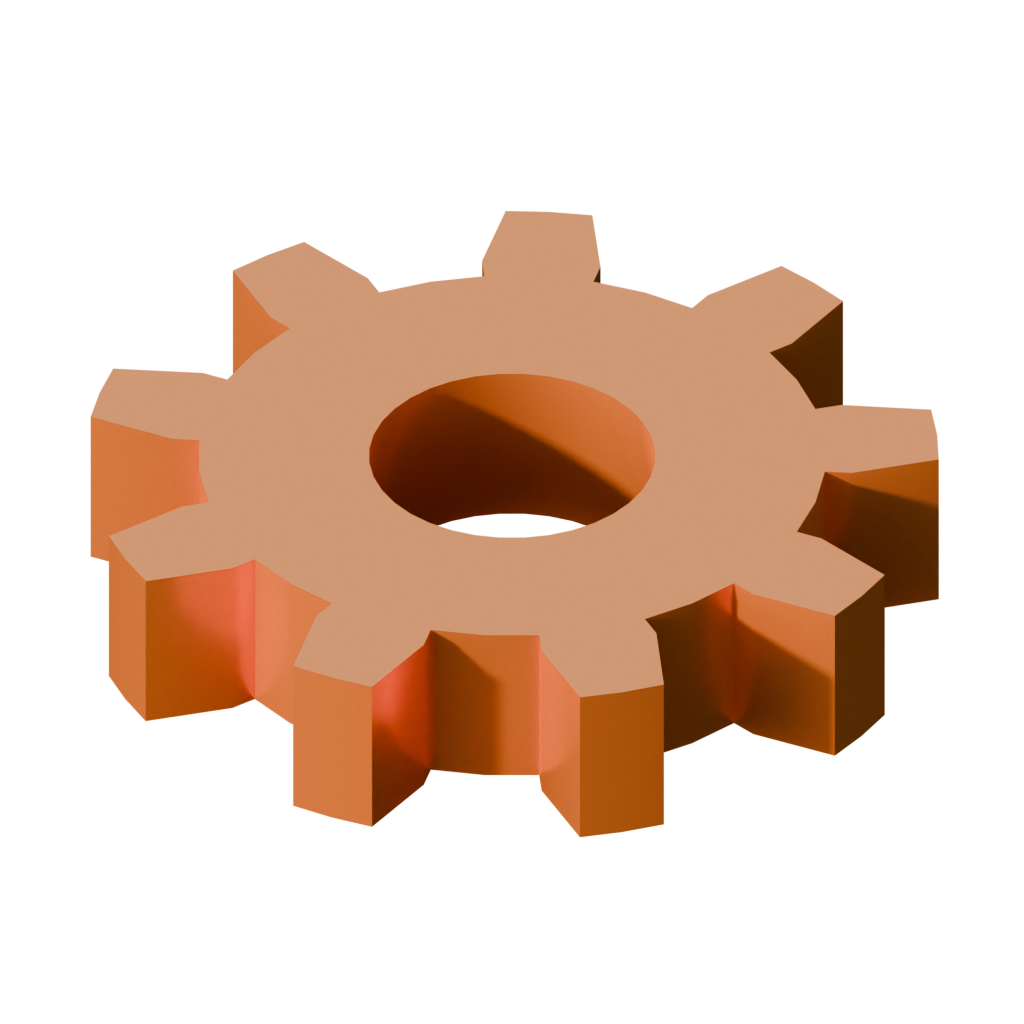
When developing Materials, it is commonplace to test their appearance using a pre-made Mesh. It would certainly be possible to use a Mesh created in a previous chapter, or use Blender's built-in test Mesh Suzanne (Add → Mesh → Monkey), but let's use something more thematic and create a gear Mesh instead. We can create such a Mesh in multiple ways: the easy way (with an Add-On), or the hard way (manually).
If one finds Blender lacking in sophistication and complexity, they can add more complexity to the workspace by installing plugins called Add-Ons. Many Official Add-Ons are pre-installed, and are simply waiting to be enabled. Let's activate an Add-On that can automatically generate gear Meshes.
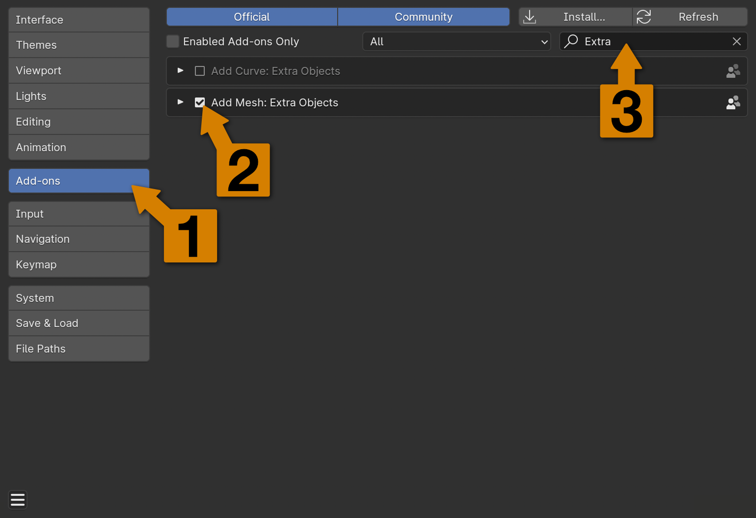
First, navigate to Blender's Preferences Menu via Menu Bar → Edit → Preferences or the keyboard shortcut [Control/Command]+[,] (the comma key). Then, find the Addons submenu in the sidebar (1), and locate the Add Mesh: Extra Objects panel, ensuring that its tickbox is checked (2). This menu is a bit busy, so using the search bar (3) can help.
Ticking the box will activate the installed Add-Ons. When activating an Add-On it may seem like nothing has happened - this is normal. Let's return to Object Mode in the Main Viewport to give it a try. Opening the Add Mesh menu (Add → Mesh or [Shift]+[A]), there are now a lot more options available, including one that generates gear-shaped Meshes!
The default gear Mesh added by this tool is a good start, but it has some potential problems. For instance, what if a different number of teeth is desired? Directly after adding a gear Mesh in any mode, a small, collapsed options menu will appear in the lower left of the Main Viewport; this is the options menu for the last tool used, in our case, the gear Mesh generator. Clicking on this widget will expand it, showing all of the possible parameters for generating a gear Mesh.

The parameters here are named according to the parts of the Mesh that they control. Notable parameters include Number of Teeth, Width and Radius, which function as one might expect, but also Dedendum and Addendum for controlling aspects of the length of the teeth.
Tip
Most tools in Blender work this way - directly after using the tool, a (collapsed) options box may appear in the lower left of the Main Viewport. Expanding this box will enable direct control over tool function, so it's not necessary (or perhaps even undesirable) to rely on cursor movement when exact values are required.
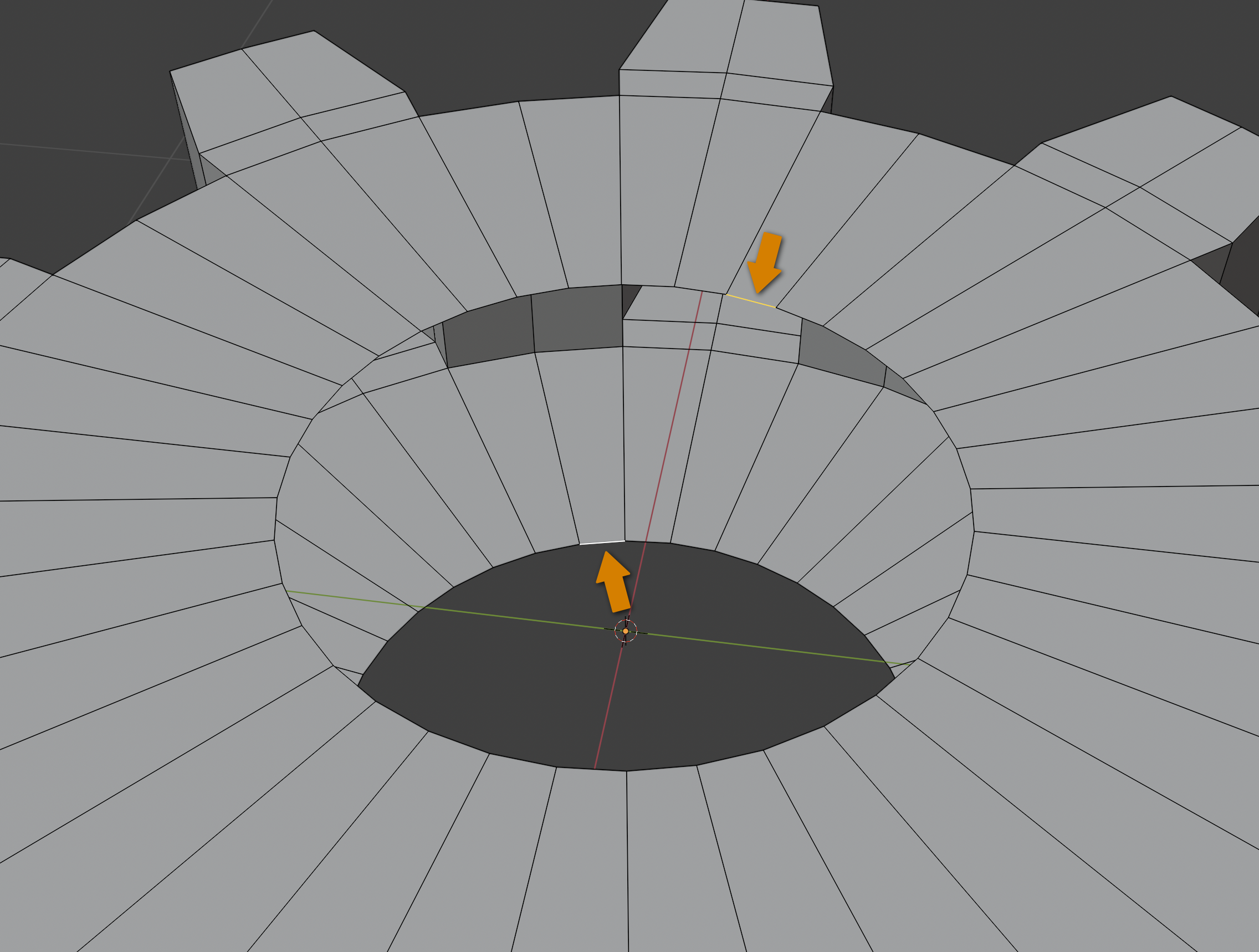
One might notice a slight problem with the generated Mesh: peering through the center, one can see the inside of the Mesh. Looking around in Edit mode, the problem becomes clear: There are no Faces on this part of the Mesh. These will need to be added manually, but fortunately Blender can make this process nearly automatic.
In Edit mode, switch to Edge Select Mode (via the Menu Bar or keyboard shortcut [2]) and select any two Edges from the two rings of edges bordering the problematic "missing" Faces. As stated previously, multiple things can be selected (or deselected) by holding [Shift] while left-clicking on them.
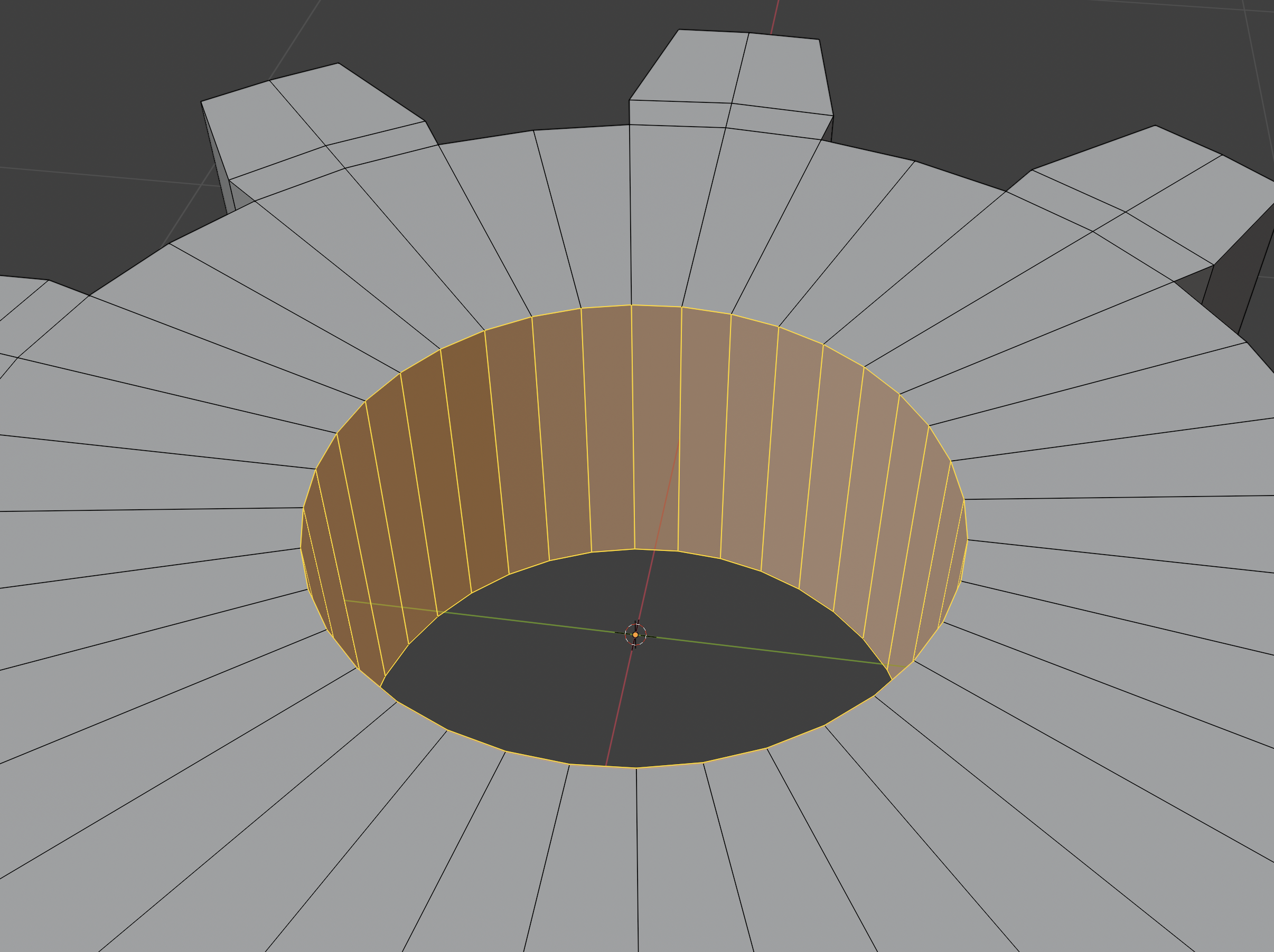
Then, navigate to the Menu Bar, then Select → Select Loops → Edge Loops. As can be seen, Blender is in most circumstances able to automatically follow and Select the connected Edges.
Tip
An alternative way of Selecting "loops" of things is by holding the [Alt/Option] key while Selecting. This works with Vertices, Edges, and Planes, and one can additionally hold the [Shift] key to toggle a loop Selection.
If Blender is unable to deduce a loop, it will instead Select as much as it can, be that a "partial" loop or simply the singular thing clicked upon.
With the two rings of Edges selected, navigate to the Menu Bar, then Edge → Bridge Edge Loops. Much better!
This is all well and good, but what if we want to create a gear entirely from scratch? This will be explored in an an upcoming section, but for now, let's use our automatically-generated gear Mesh (or Suzanne) to develop a metallic material suitable for rendering for Factorio.
Blender offers a default Workspace designed for developing Materials: the Shading Workspace. This Workspace, like all Workspaces, is offered among the tabs at the top of the Menu Bar.
The Shading workspace has two new areas of interest:
- A 3d
Viewportfor previewing models and Materials. - The
Shader Editorfor developing Materials.
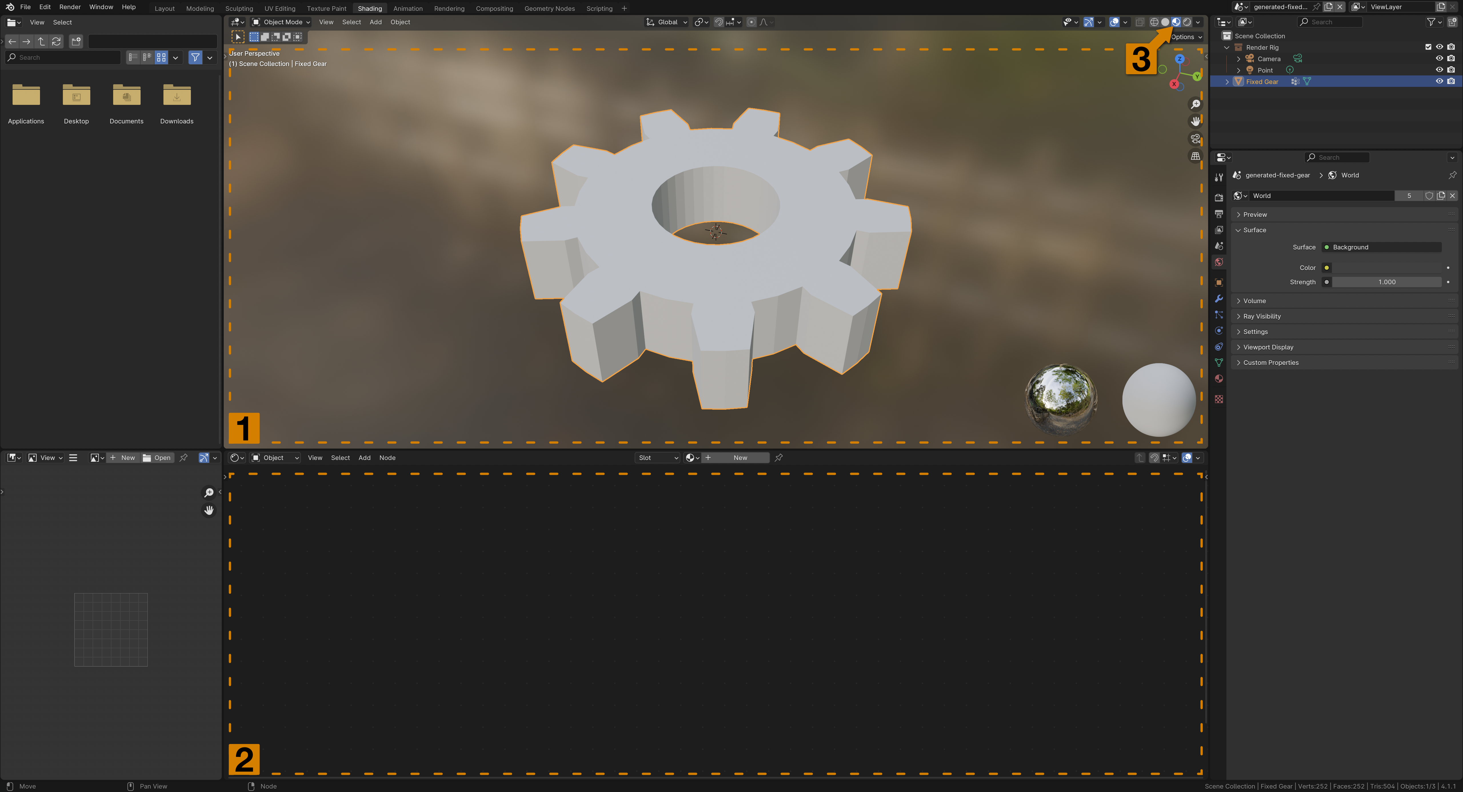
The other areas, a File Browser and Image Editor are not of interest at the moment, and the Scene Outliner and Properties Panel should be familiar from the other Workspace modes. Notice that the Viewport of the Shading Workspace is using a different rendering mode (3). Here, it is in the Material Preview mode, which is perfect for our purposes. If desired, one can switch to Rendered (the right-most icon) for an in-editor approximation of what the final render will look like.
Tip
It's possible to change the shading mode in any Viewport, regardless of Workspace - even in Layout or Modeling. This is because the shading mode is a setting of the individual Viewport, and not of the Workspace itself - each individual Viewport across one or many Workspacess can be set to a different mode.
Right now, the gear Mesh is using a default, built-in Material. It would be better if it were more metallic, so we will have to create a new Material.
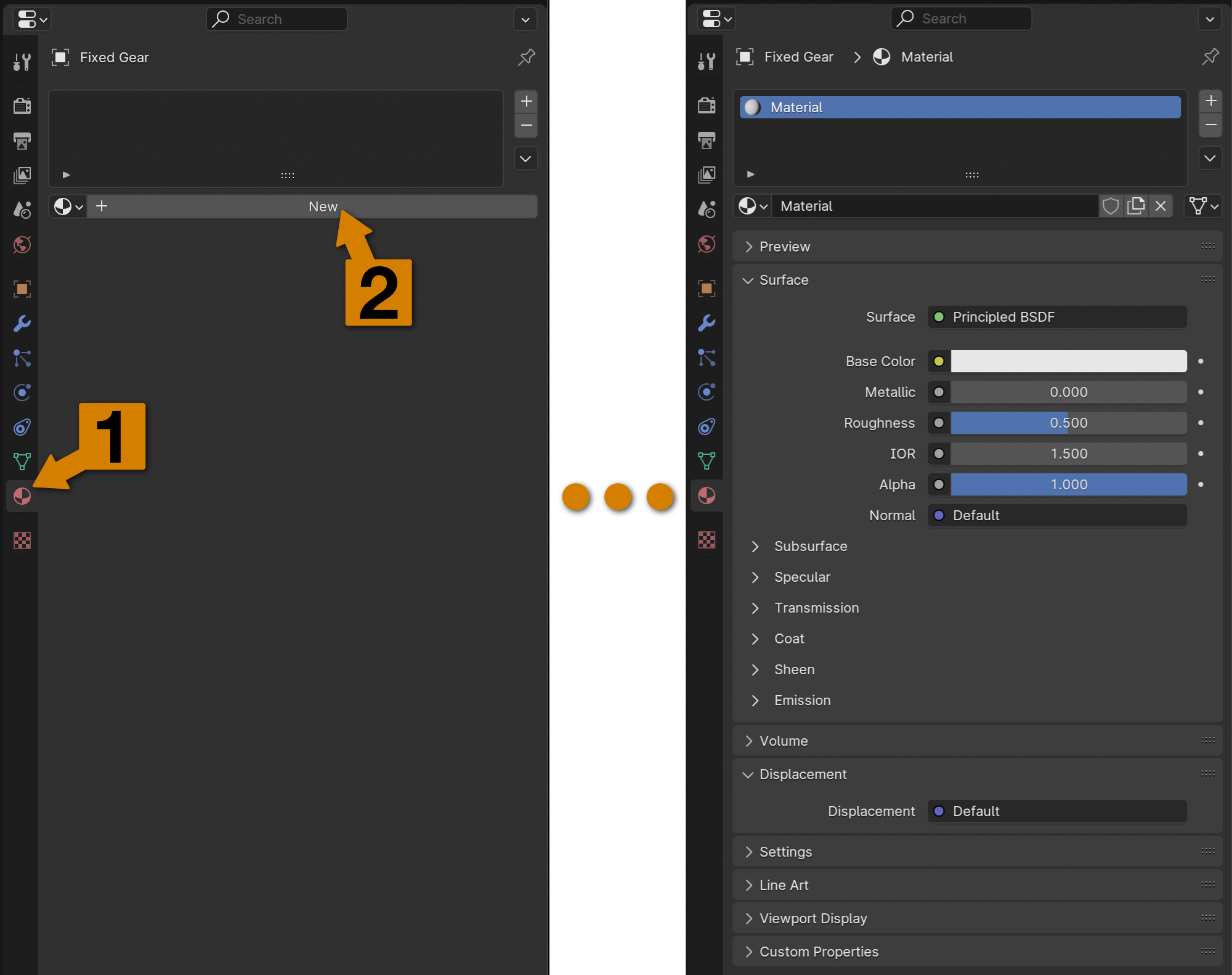
First, select the gear Mesh in either the Viewport or Scene Outliner. Since Materials are applied to relevant Mesh geometry, it wouldn't do any good to create a new Material without applying it to our gear. Then, in the Properties Panel, locate the Material tab (1) - it looks like a checkered sphere. In this tab, click the New button (2).
Several things probably just happened at once - First, the Material tab of the Properties Panel just got a lot more busy, and second, the Shader Editor probably has some more things inside it as well. Let's ignore the Shader Editor for now and focus on the Properties Panel:
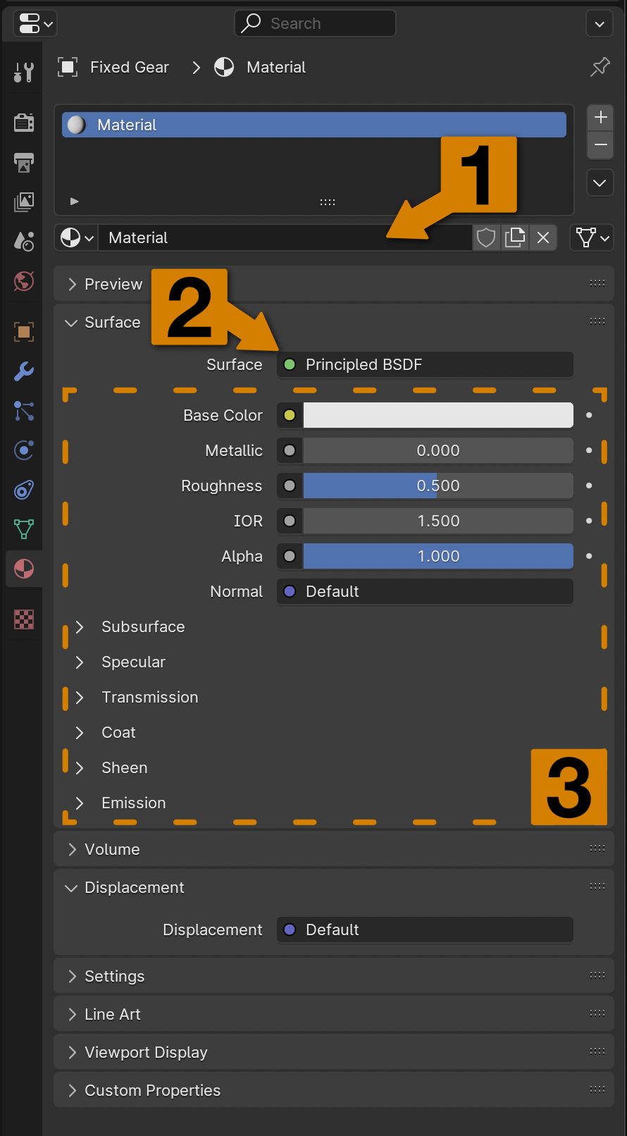
There are three areas worthy of note at this time:
- A dropdown menu and text field for giving a name to the Material, or choosing what Material should be applied to the Selected Object.
- The
Surfacefield, which is a dropdown menu which selects what kind of underlying Shader is used to draw the Material. - Material parameters, which are provided by the underlying Shaders - different Shaders have different capabilities, and thus offer different parameters.
A Shader is a special program that is run during rendering that Blender uses to simulate the properties of an Object. A Material may be made of one or many Shaders that all contribute to how Blender will render the Object. Right now, this Material consists of exactly one Shader, the Principled BSDF.
Note
"BSDF" stands for "Bidirectional Scattering Distribution Function", which is an industry term referring to a class of mathematical functions describing how to simulate the way light interacts with a surface. The "Principled" part refers to the fact that Blender tries to base the math on physical principles as much as possible - thus, "Principled BSDF" is a Shader Program based on physical principles that instructs the renderer how light paths should interact with the surface.
The Principled BSDF, based on representing physical properties, offers many parameters, with some being more intuitive than others. If we want to turn our gear Mesh into a copper gear, then it seems sensible enough that we would want to change the color and "metallicness" of the Material, so let's give that a try.
Tip
The Blender Documentation on the Principled BSDF describes what each parameter does in detail, with image examples.
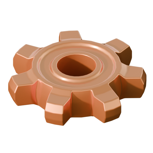
Let's begin by setting the Base Color property - simple enough, this parameter sets an underlying color. But what if we want the Material to seem like it is made of metal? Surely the Metallic parameter is what we seek?

It seems that the Base Color property does as expected, and the Metallic parameter seems to be doing something, but it's not obvious what - even when set to the "safe" maximum value of 1.0. The Material Preview in the Workspace viewport probably isn't producing the desired effect, and the actual render doesn't seem to be faring much better. According to the Blender Documentation, these are indeed the correct parameters to use - so what's happening?
The answer is somehow both subtle and obvious: because Blender works by simulating the way light interacts with Objects in a Scene, if there is nothing else in the Scene then it doesn't matter how reflective we make our copper gear since there are no other things to reflect. Our little universe consists of only one lonely gear; to simulate realistic lighting and reflective surfaces (such as metals) we need to add more to our Scene.
Unfortunately, it isn't enough to simply set the physical properties of the Material; since Materials interact with simulated light rays pathing throughout a Scene, it will help give the appearance of realism by simulating an environment for our Objects to occupy.
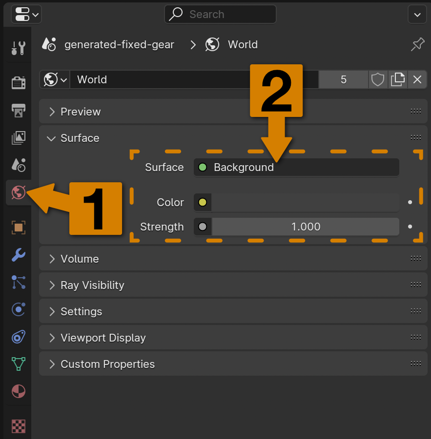
Naturally, Blender offers facility for simulating environments. In the Properties Panel, locate the World tab (1) - the icon resembles a globe. Then, take a look at the parameters inside this panel (2). The Blender World is also simulated using Materials: just as a Material determines how the surface of an Object should interact with a simulated ray of light, so too does the Material of the World determine how the environment should interact with simulated light rays. In this case, the default is to shade the World as a uniform, grey void - as specified by the Color parameter. It's possible to change this parameter to another color, but this wouldn't necessarily produce the desired result either.
Instead, let's simulate a simple environment with an automatically generated Sky Texture. Observe that next to the Color field there is a yellow dot - this denotes a kind of programmable input. Clicking this dot opens up a menu with many options - click Sky Texture.

With the newly-created Sky Texture attached to the Color input of the World Material, several more options become available.
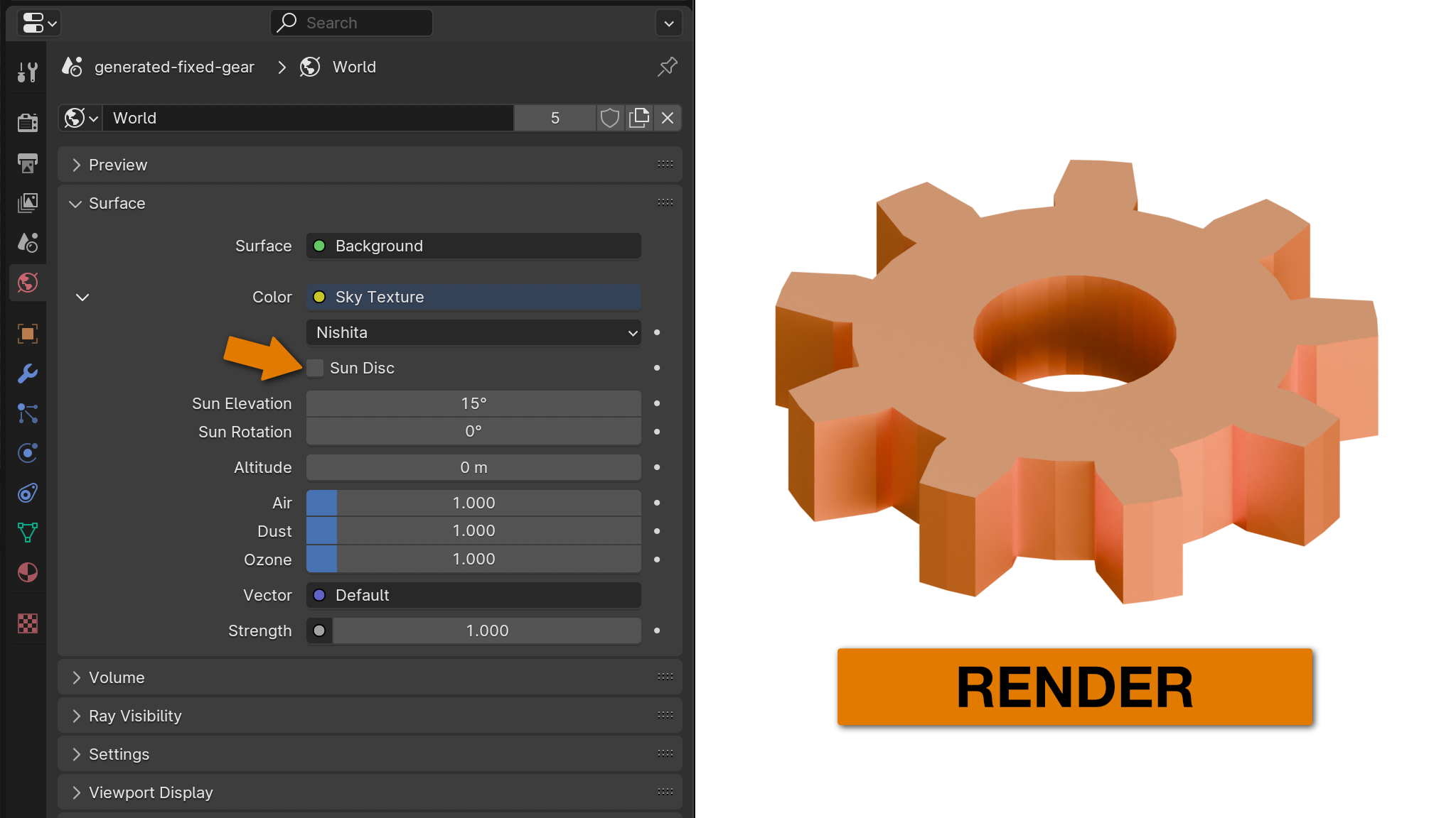
The top dropdown menu allows one to select from several methods for simulating an artificial sky. They are named after the authors that devised the algorithms, and each has different qualities and capabilities, such as simulating the position of the sun and composition of the atmosphere. Disabling the Sun Disc and making no other changes to the Nishita generator, the render is already looking much better thanks to the ambient lighting provided by the simulated sky:
Feel free to experiment with the other properties of the sky texture generator, or try using a different generator besides the default Nishita.
Tip
The Sun Elevation parameter also seems to adjust the brightness and color of the scene lighting, why is that? Because this is also a simulation of time-of-day, and when the sun is lower in the sky (i.e. at a lower elevation in the sky dome), the ambient light is different. Morning, noon, and evening all have different lighting qualities that are represented in the simulated Sky Texture.
Sky Textures are a nifty feature, but they are generally lacking in detail. In practical terms, this means that the reflectivity of isolated Objects isn't very apparent, as there is no detail from the environment to reflect.
An HDRI (High Dynamic Range Image/Imaging) is a sort of 360° picture of a real environment that Blender can use in the World Material to simulate that environment. Fortunately, there are quite a few nice, free HDRI resources on the internet. HDRI Haven hosts exclusively free, public-domain HDRIs, and Poly Haven also offers a selection of free HDRIs (though the licenses may vary).
By selecting an HDRI that approximates the environment we wish to simulate, we can make our renders look like they were captured in that environment - lighting, reflections and all. Even if the materials involved in the render are not perfectly smooth or reflective (that is, they are not mirrorlike), the ambient lighting provided by the HDRI adds realism and character to the final render that is otherwise difficult to replicate.
Tip
It isn't feasible to capture an HDRI of Nauvis, but there are many lovely HDRIs online that are similar in color palette. Since the final sprite is likely to be quite small in-game, just choose an HDRI that seems in-character. Most of the reflective surface details will be destroyed for two reasons: the image size will be reduced before importing into Factorio, and we generally won't be creating perfectly smooth, perfectly reflective (mirrorlike) materials. For these reasons, it also really isn't necessary to download the most high-resolution HDRIs - 2K is usually sufficient.
I've selected a few interesting-looking HDRIs below - try any or all!
- Dead grass, rocks, and a low sun
- Between mesa-like rock formations
- A rocky hill with overcast skies
- Rocky cliffs overlooking a valley, with minor buildings
Tip
Of course, don't be afraid of selecting an "indoor" HDRI instead. Most of the time, the details of the environment won't be directly visible anyways - the purpose is to add character to the lighting of the Scene, so if it looks good, use it!
Once a suitable HDRI has been downloaded, it must be imported into Blender. This is done the same way as with the Sky Texture: go to Properties Panel → World, and then find the Color field. Click the yellow dot, and instead of Sky Texture choose Environment Texture, then click Open and import your downloaded HDRI.
Once the HDRI is loaded, then while rotating the view around in the Viewport, if the Material is metallic enough and smooth enough (high value for Metallic and low value for Roughness), it should be possible to make out reflections in the Material from the environment texture.
Tip
The lighting in an HDRI might be otherwise ideal, but coming from the wrong direction. It's possible to fix this by simply relocating the Active Scene Camera, but another way can be found in the Appendix of Helpful Techniques
There are a few other minimal-effort ways to adjust the way that a rendered Scene looks, and they involve Blender's simulation of real-life camera function.
Just as in a real camera, Blender's Cameras can simulate Exposure. In a real camera, Exposure refers to the degree to which captured light is permitted to affect the film or sensor - as these elements are exposed to light to produce the image.
To adjust simulated Exposure in Blender, navigate to the Properties Panel → Render Properties → Color Management → Exposure. This is also where simulated film contrast (the Look parameter) can be adjusted for a more dramatic lighting effect.
Sometimes it's easier to understand something with pictures rather than words - below is a table of the effects of Exposure and Look on a simple Scene with otherwise identical lighting:
| Low Exposure (-2.0) | Normal Exposure (0.0) | High Exposure (2.0) | |
|---|---|---|---|
| Low Contrast |  |
 |
 |
| Normal Contrast |  |
 |
 |
| High Contrast |  |
 |
 |
Note
Since the end result we're after is just a flat image, there's really no wrong answers for lighting configuration as long as you like the result. The methods discussed so far - adding a Sky Texture or HDRI - are the easy shortcuts, but they are not the only ways to add lighting to a Scene. There are many in-depth tutorials on the internet for how to light Scenes in Blender, but I have found that just these few tools alone are sufficient to produce interesting and reasonably-well lit renders for Factorio.
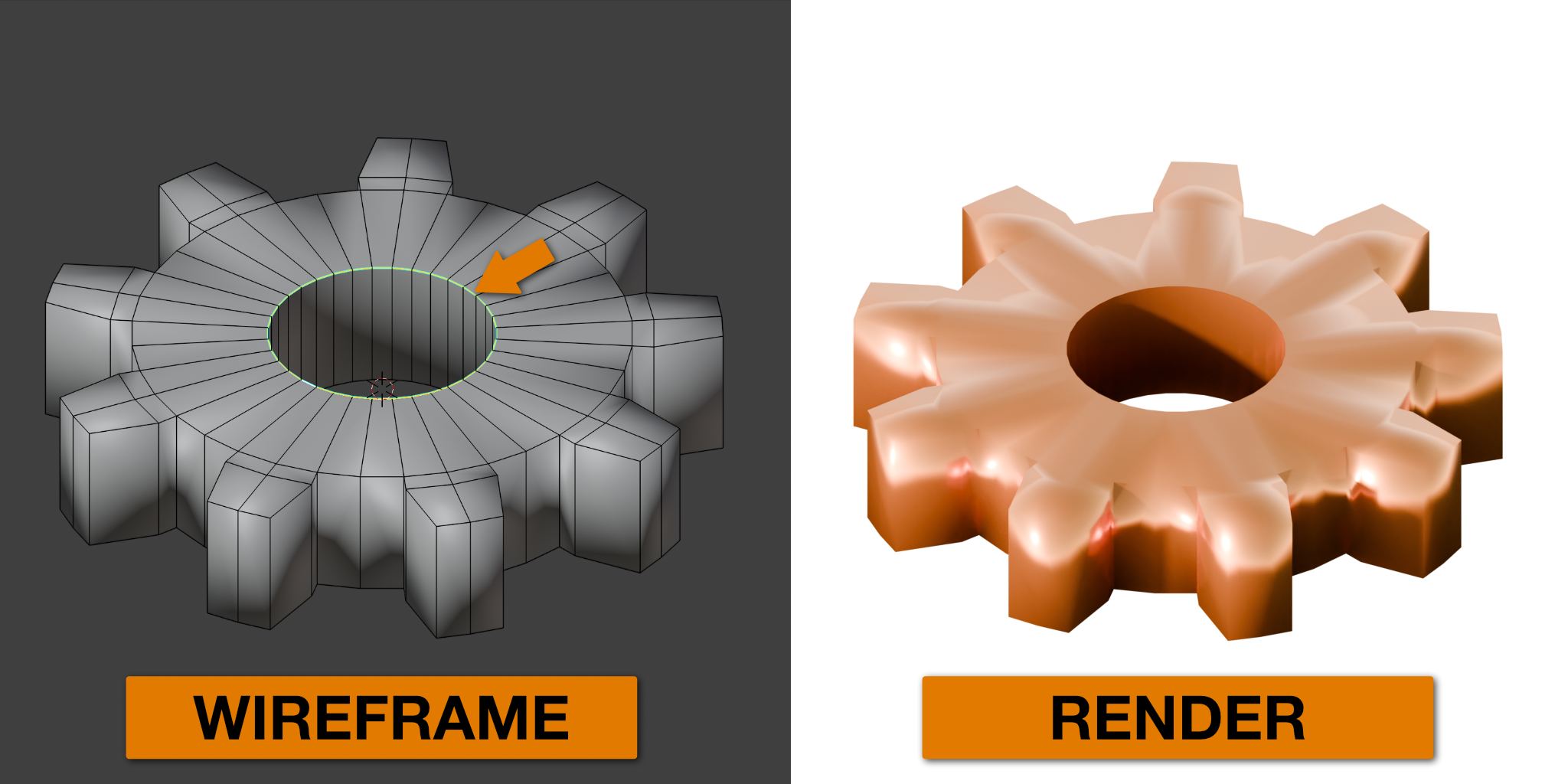
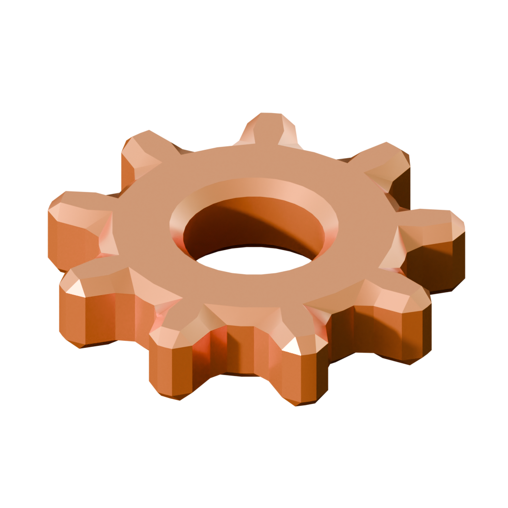
There is another aspect to controlling how an Object is rendered, and it does not necessarily have anything to do with a Material. If one carefully examines the following render against its wireframe counterpart, an observation can be made: The rendered gear has undesirable flat areas, since in the original Mesh, those areas are flat Faces.
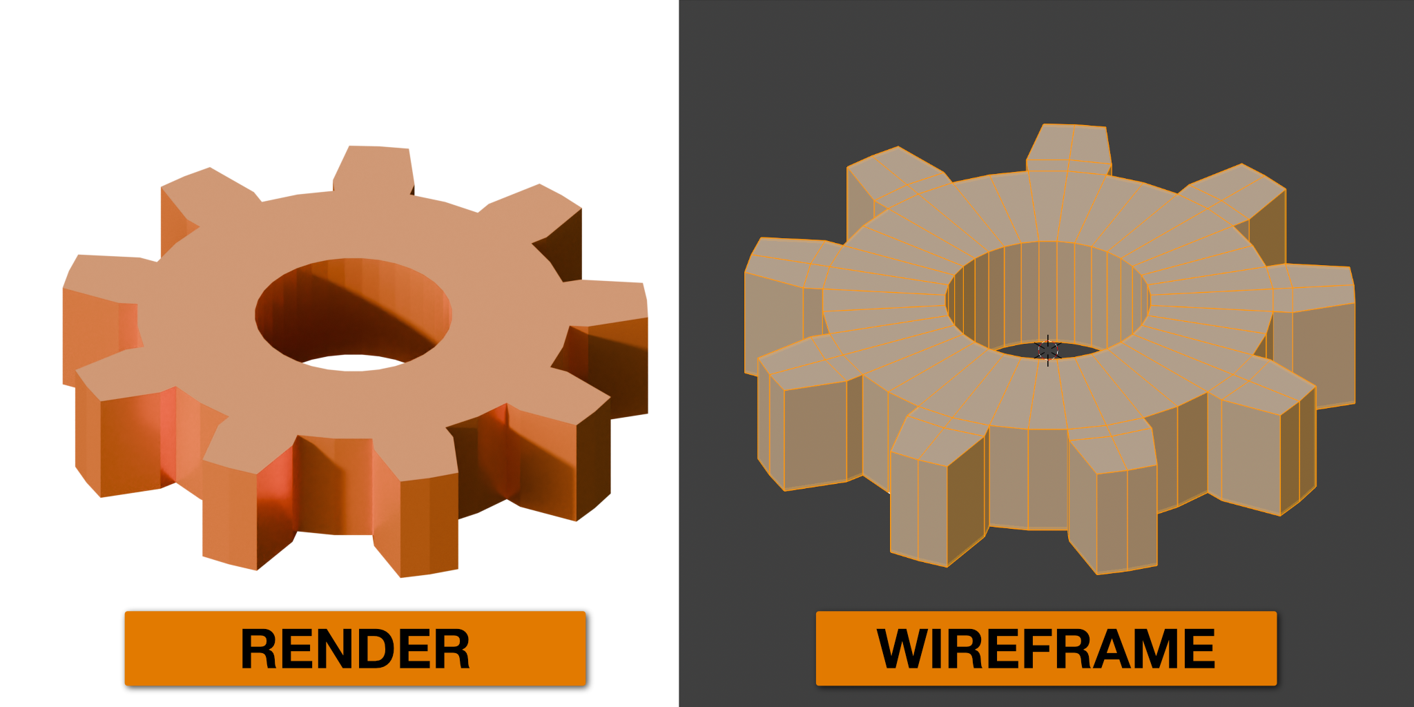
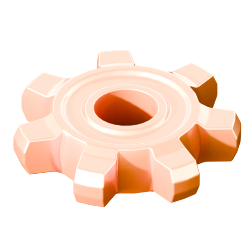
These flat areas generally do show up when the sprite is resized, and it would be better if these parts formed a smooth contour. To do this, we can mark those Faces for Smooth Shading. In Edit mode in any Viewport (Layout, Modeling, Shading, or otherwise), Select all Faces of the Mesh and then right-click, selecting Shade Smooth.

The result looks awful! The entire surface is melding together as a smooth contour - is there a way to tell Blender which Edges to keep sharp, and which to Smooth? There are multiple ways, and one of them is with Mark Sharp. In Edit mode, select an Edge or set of Edges, then right-click and select Mark Sharp. As an experiment, one might try this with one of the Edge Loops forming the axial hole of the gear:
This works, but manually marking various Edges sharp might be a little tedious with a more complex Mesh. Furthermore, it might not be possible at all if the Mesh has dynamically-generated elements - since the desired Edges might be dynamically generated and therefore not exist on the original model.
Fortunately, there is a Modifier that can perform this operation automatically. The Smooth By Angle Modifier will effectively mark any Edge as sharp if the angle it forms between the adjacent Faces meets a particular threshold. With the desired Object (our gear Mesh) Selected, go to the Modifiers panel, and then navigate to Add Modifier → Normals → Smooth By Angle.
The effect is more obvious when combined with a Bevel modifier - please give it a try!
Note
What does this Modifier have to do with Normals? Blender - and most computer 3d graphics - use Normals to calculate how light should interact with a thing. Since a Normal is the Vector perpendicular to a plane, the Normal can be used to determine at what angle a plane is relative to the light source and observer - put another way, it simulates how light would "bounce" off the surface between a light source and the observer.
By default, Blender simply uses the actual Normal of a Face to calculate how light would bounce off of it, but we can ask Blender to pretend that the Normals vary across the surface of the Face on a minute level, smoothing them out and thereby altering how simulated light rays reflect off of these Faces.
This also goes some way to explain the mysterious Harden Normals option in the Bevel modifier's Shading parameters.
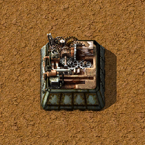
This concludes Chapter 3. Hopefully, we've made some interesting gear Meshes with a shiny metal Material. There's perhaps a stylistic problem with these gears - they're a bit too clean-looking. In Factorio, even freshly-smelted metal plates have a bit of grunge to them. Fortunately, Blender can solve this problem too. In the next chapter, we will explore making more sophisticated procedural Materials using the Shader Graph system, automatically adding grit, grunge, and rust for a more Factorio-esque aesthetic.
Note
The remaining sections are optional, and serve as additional information as to how to create interesting gear Meshes manually.
Anything that is possible to do automatically in Blender is theoretically possible to do manually (but it might be more time-consuming). Creating a gear Mesh from scratch is not very difficult, but it may require learning a new tool.
As the adage goes, let us begin with the shape that is closest to our desired goal: A gear is sort of like a broad, flat, cylinder, so let us begin by adding a cylinder Mesh the same way that other Meshes are added: Add Mesh → Cylinder. This time, however, let's expand the Tool Options panel that appears in the lower left of the Main Viewport, and change the Depth option so that the generated cylinder is flatter:

Since we're going to turn the Faces on the sides of the cylinder into the gear's teeth, it may also be a good idea to set the Vertices parameter depending on the desired arrangement of teeth, as this controls the number of Vertices for each circular face of the cylinder, and therefore the quantity of Faces on each side. For instance, a setting of 30 will yield 30 side Faces, meaning a patterned arrangement of 3-wide teeth and 2-wide gaps is possible (6 teeth * 3 + 6 gaps * 2 = 30 faces).
Tip
It would also be possible to add a cylinder, and then Scale it on the Z axis - one should always choose the workflow that makes most sense to them.
Next, let's select some of the Faces on the side of the cylinder to be turned into the teeth of the gears. One may select alternating faces, or groups as preferred; depending on the number of Faces on the side, different evenly-sized groupings will be possible. Next, let's use a variation of the Extrude tool to turn these Faces into the teeth of the gear. But we can't just Extrude all these Faces in the same direction (Feel free to try it - don't forget to Undo after!). Instead, we need to Extrude radially, in the direction that each selected Face is facing. Let's use a variant of the Extrude tool designed for situations like this: In the Toolbar, click and hold on the Extrude tool, then click on Extrude Along Normals.
There's something a little off about this shape, however - the teeth are wider at the ends than at their base. It would be possible to Scale them all individually (using the Tool Options dialogue to ensure consistency), but let's Scale them all at once using a different Transform Pivot. At the top center of the Main Viewport there is a mysterious array of icons. These control the reference space for Transformations - it's a vector math thing. We want to scale the selected parts towards themselves, so let's open the Transform Pivot menu (1) and select Individual Origins (2).

Now, when these selected faces are Scaled, the selected regions will Scale towards themselves individually rather than the centerpoint of all of them. This might be easier to understand with direct experience, so try Scaling the teeth faces using both the default Median Point and then Individual Origins in the Transform Pivot menu - but don't forget to set it back to the default when finished.
Note
All of Blender - and indeed, all of computer graphics technology - boils down to complex Vector math. Understanding these topics on a mathematical level isn't necessary for success with Blender, and it's entirely possible to get a feel for how the tools work without knowing how they work on a technical level.
However, if one wishes to ascend to Wube levels of technical aptitude, learning more about these concepts is a good first step on that journey - but that is out of scope for these tutorials.
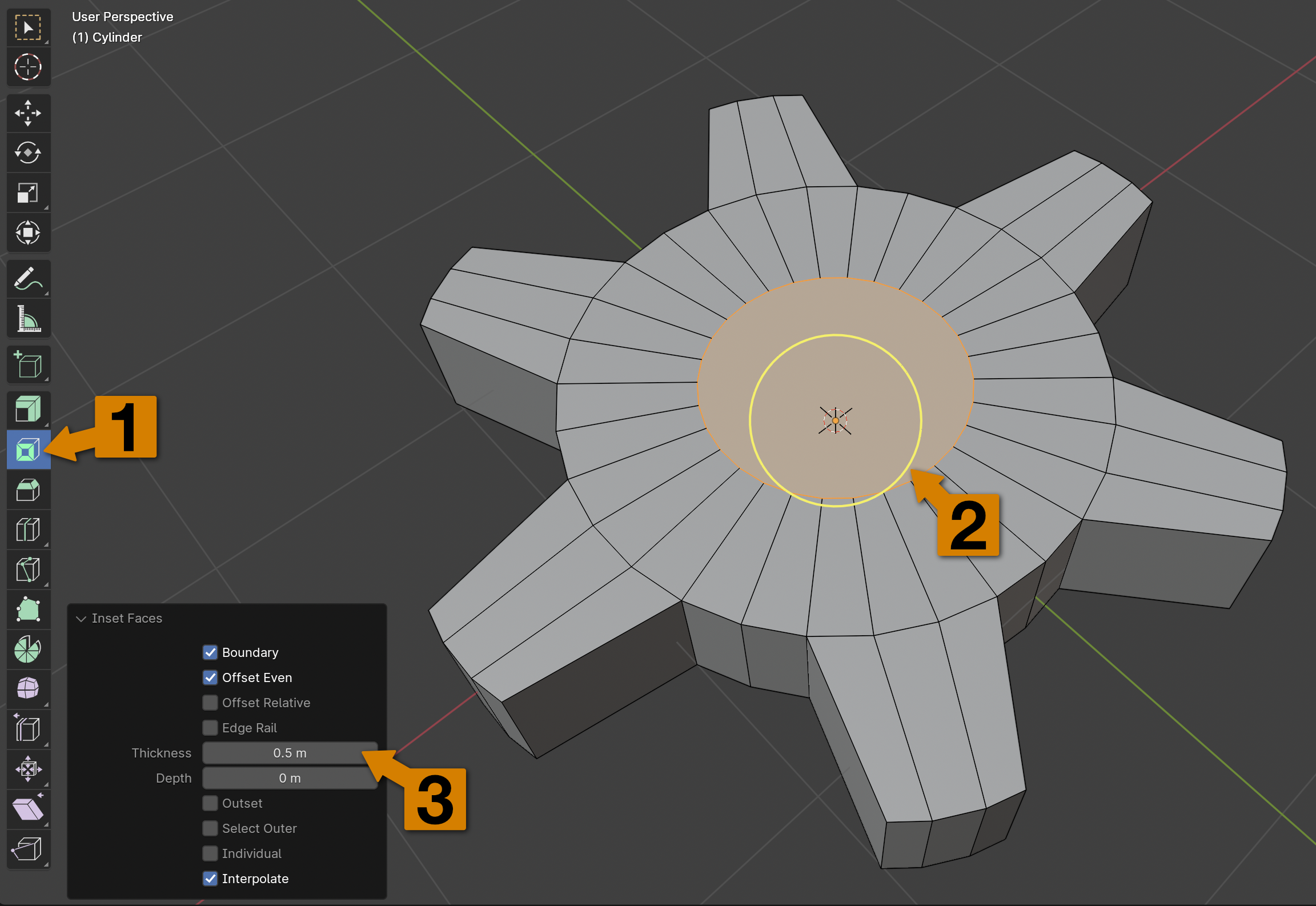
There's still a problem with this Mesh: there is no hole for an axle to go through. This is a relatively easy fix, by using the Inset Faces tool to inset the circular faces, then deleting the smaller faces and finally filling in the missing Faces. After Selecting the top and bottom circular faces of the gear Mesh: from the Toolbar, select the Inset Faces tool (1), and then click and drag on the yellow circle that appears (2), if desired setting a specific inset distance in the Tool Options dialogue (3). The keyboard shortcut to inset faces is the [I] key. This will create an "inset" of a smaller circular polygon within both faces.
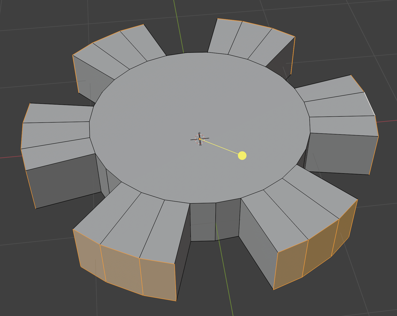
Next, let's delete these two inset Faces: after ensuring that both Faces are Selected, right click one of them, then choose Delete Faces. Alternatively, one can use the keyboard shortcut [X], then choose Delete Faces. Just like with the automatically generated gear Mesh, we can now ask Blender to create Faces along the two inner circles with Bridge Edge Loops as previously.
Of course, it is possible to combine all the techniques learned to far: Creating a simple gear Mesh by hand or using the generator, tweaking the surface details manually, and adding Modifiers to finish.

Can you guess how it was made? (Click for explanation)
Here's how:- Add a new gear Mesh with 7 teeth.
- Fill the missing axle Faces using Bridge Edge Loops
- Use Loop Cut to add two horizontal loops around the perimeter of the gear
- Scale the newly created middle section of the perimeter, creating a bulge
- Scale the top and bottom flat ring of Faces on the Z axis, making the gear wheel thicker than the teeth and creating an interesting slope
- Use Inset Faces on the top and bottom flat ring of Faces to create an inset ring
- Move both the top and bottom inset rings upwards, creating two styles of gear in one (reversible!).
- Add Bevel and Smooth By Angle modifiers to taste
Note
If you'd like to download the Blender file I made for this chapter, click here. Each of the relevant models is in a different Scene for tidiness, refer to Chapter 1 for instructions on how to switch scenes.