-
Notifications
You must be signed in to change notification settings - Fork 32
STM32F4DiscoImuDemo
The STM32F4-Discovery board unfortunately has a design decision which prevents us from stacking it on the Element14 Ethernet board and using both Ethernet and the onboard accelerometer at the same time. This is unfortunate. However, with some relatively simple modifications, we can move one of the accelerometer bus lines to a different pin on the STM32, and use both peripherals simultaneously. The following steps show how to do this:
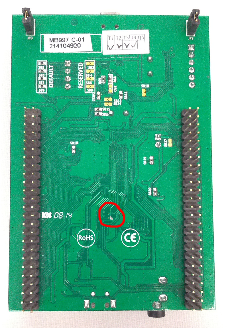
Here is a photo of the bottom of the STM32F4-Discovery board, with the region of interest circled:

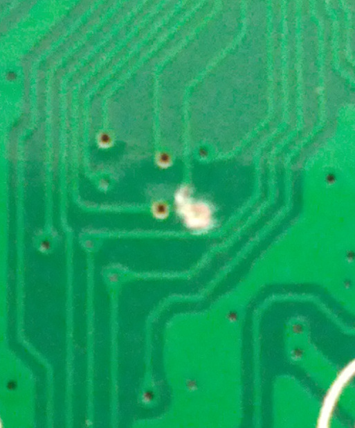
Here is a close-up photo of the trace cut. (Sorry, old cellphone camera... if you need a better photo, let me know and we'll take a microscope photo.)

Everyone has their own strategy for how to do this, but I like to use an exacto knife and make two cuts in the trace a few millimeters apart. Then, use the blade to remove the trace copper between the cuts.
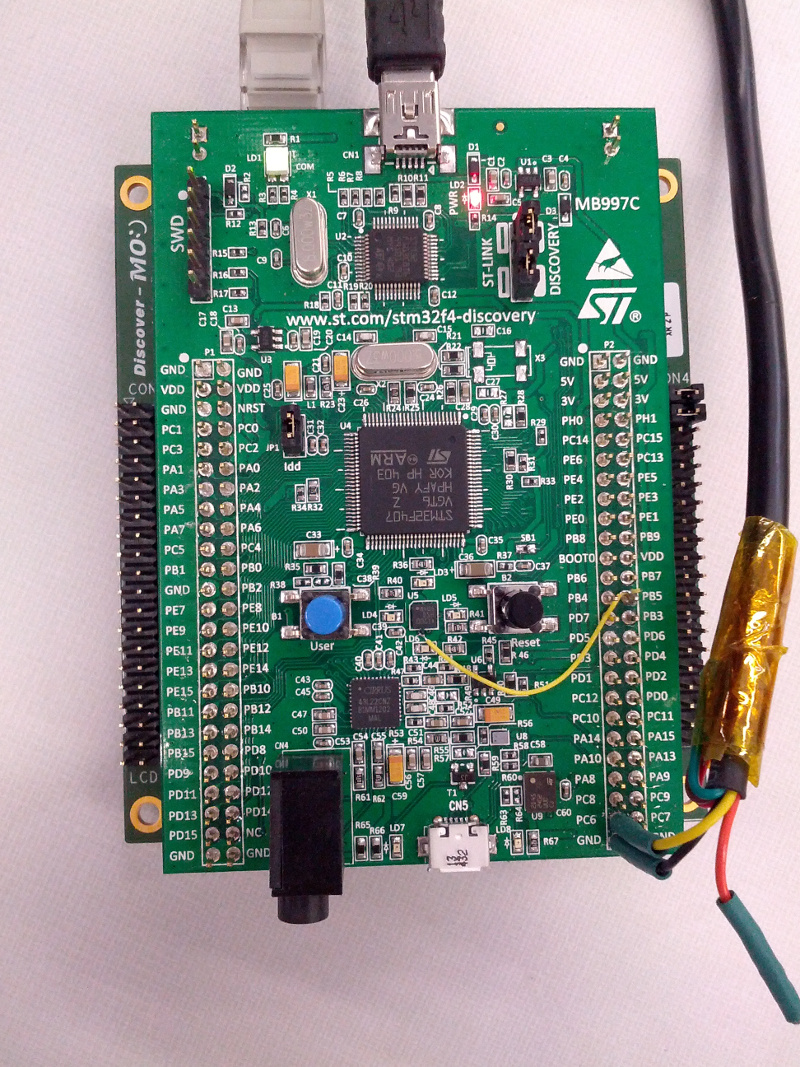
The next step is to jumper the newly-freed accelerometer SPI MOSI pin to an unused STM32F4 pin which can also multiplex the SPI1 MOSI signal. We'll use pin PB5. Although PB5 has a nice big header exposed on the STM32F4-Discovery board, the accelerometer MOSI line is a bit more difficult to access. I just scraped the soldermask off one of its vias and then soldered a rework wire from the exposed via to the PB5 header. Here is the finished product:

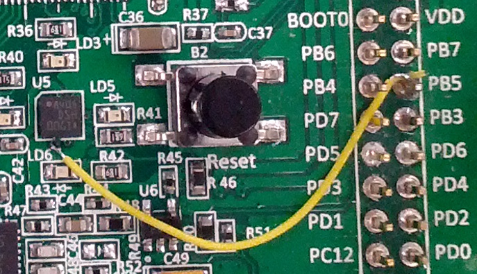
Here is a close-up photo of the jumper. (Sorry, old cellphone camera... if you need a better photo, let me know and we'll take a microscope photo.)

cd ~/freertps
make program-imu-stm32f4_disco-metal
cd ~/ros2_ws
source install/setup.bash
imu_listener__rmw_opensplice_cpp
You should see a stream of accelerometer readings printed to the console, and as you wave the STM32F4-Discovery board around, they should change accordingly. Hooray!