-
Notifications
You must be signed in to change notification settings - Fork 0
Project Hierarchy
Here is an example of the project hierarchy for a CodeModeler project named “CarRental” in the Solution Explorer:
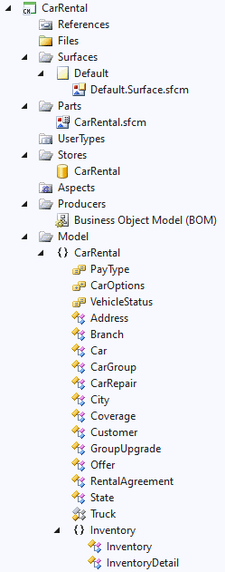
The root nodes References, Files, Surfaces, Parts, UserTypes, Stores, Aspects and Models folders are always present and are detailed in the following chapters.
The References folder node holds entries in a project that contain the information that CodeModeler needs to display or build the project. By default, a CodeModeler project doesn’t contain any reference and (contrary to other project types, like C# projects) doesn’t need any.
The current version of CodeModeler only supports .NET class libraries (assembly) references, compiled or as a project in the same solution. These libraries are used to resolve external .NET types used in the project (property types, etc.), and compiled .NET CodeModeler Aspects.
To add a reference, you can use the References node context menu and select the standard “Add Reference…” menu item.
The Files node can contain any extra files that can be useful for the developer to carry with the project (for example template text files). By default, this folder doesn’t contain anything.
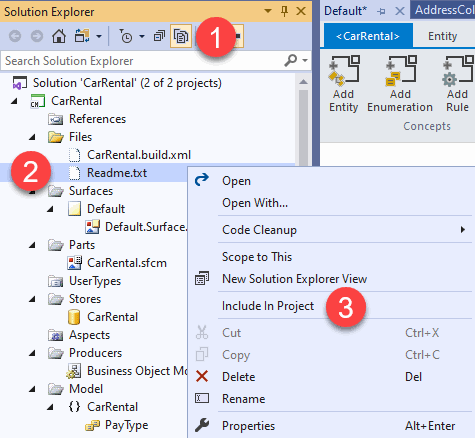
To add a custom file in that node, put a file in the project physical folder (outside of Visual Studio), and then, from in the Solution Explorer click on “Show All Files” and “Include in project” on the file that has appeared, like here with a “readme.txt” file:
There’s usually a file that ends with build.xml in your project file. This is the output of the last CodeModeler build. You can open it using a standard text editor as it can be useful (you can also delete it as it’s just an output file for CodeModeler), but don’t include that file in the Files folder node.
The Surfaces node holds the list of design surfaces used in the project. A surface node is associated with a CodeModeler-specific Visual Studio editor window that displays:
-
Namespaces, containing types;
-
Types, entities and enumerations. The list of types that are visible in the surface is defined by an EPath equation. The default surface equation contains all types.
-
Relations, between types;
-
Sticky yellow notes, that Visual Studio users can add to a surface;
The editor can be simply invoked using a double-click on the surface node in the project hierarchy. The window that opens in Visual Studio is a document Window, so it can be dragged on any screen. If you use a dual monitor setting for example, you can drag the surface editor (using standard Visual Studio mouse movements) on the secondary screen, like this:

A surface node definition (not the types it displays) is stored on a specific CodeModeler Part (an Xml file, see next chapters) that will contain the surface EPath equation (defining the types selected in that surface), the sticky notes it contains, and the visual coordinates of all shapes positions.
There’s always one “Default” surface in a project created with Visual Studio. That default surface cannot be deleted and the list of visible concepts in it cannot be changed, it always shows all entities and enumerations from all namespaces.
Independently of Visual Studio, a CodeModeler model is physically stored in a set of one or more “part” files. This set of “part” is named a CodeModeler package. Part are Xml files with the .sfcm file extension. A model always contains at least one part (so, one physical file).
The Parts project node contains one child node per constituting project part.
In the Visual Studio environment, any CodeModeler project also contains two other files aside the main part file:
An Xml file with the .sfcmproj extension (for example “CarRental.sfcmproj”) which contains an MsBuild-compatible project definition.
Another part file named “[name].Surface.sfcm” which contains the design surface definition of the [name] part (So, the “Default” surface associated part name is always “Default.Surface.sfcm”). Part files associated with a surface are not shown under the Parts node, but under the corresponding surface node.
The UserTypes project node contains one child node per UserType. UserTypes are useful for reusing types “derived” from standard types in many places.
To create a new UserType, you can use the *UserTypes *node context menu and select the “Add New UserType…” menu item. You must give it a name, and once the UserType has been created, you can set its properties using the standard Visual Studio Property Grid.
The Stores folder node contains one child node per Store. A CodeModeler store is a concept that is associated with a database connection string.
To create a new store, you can use the Stores folder node context menu and select the “Add New Store” menu item. You must give it a name, and once the Store has been created, you can set its properties using the standard Visual Studio Property Grid. The most important property is the “Default Connection String”.
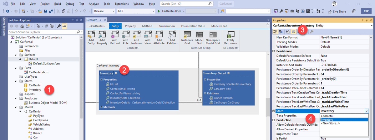
For example, in the following image:
-
Create a new store named Inventory;
-
In a design surface, select an entity named Inventory;
-
Use the “Advanced Properties” panel of the Visual studio Property Grid, otherwise you won’t see the Store property;
-
Associate the Inventory store to the Inventory entity:
There’s always one default store in a project created with Visual Studio, named after the project name. That default store cannot be deleted.
The Aspects folder node contains one child node per aspect. By default, this node contains nothing. Aspects in Visual studio are covered in this Integrating an Aspect with Visual Studio.
The Producer project node contains one child node per producer added to the project. By default, this node contains nothing, which means a “Build” command will produce nothing either. To produce something, you must add at least one producer.
To add a new Producer, you can use the Producers * folder *node context menu and select the “Add New Producer” menu item. You will then be presented with a dialog box like this:
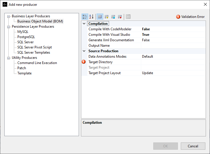
This dialog box displays the list of known producers on the left, organized by category, and the properties of the current selected producer on the right, in the property grid that you can see in Visual Studio. The property grid displays a “Validation Error” because in this example, we have not yet decided where to put the generated files.
This property grid has also an “Advanced Properties” tab available (click the yellow plus in its header) to configure the selected producer’s advanced properties.
It’s possible to integrate a custom producer to this dialog box. This is explained in Developing a Custom Producer.
The Model folder node contains a hierarchy of project-defined types (entities and enumerations), organized by namespaces. For example:
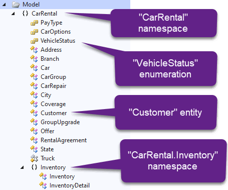
From the Model node context menu, the following actions are possible:
-
Add a new entity to the model;
-
Add a new enumeration to the model;
-
Add a new part file to the model, from a Visual Studio template. Out-of-the-box CodeModeler doesn’t currently provide any Visual Studio template part;
-
Add an existing part file to the model. The part is a .sfcm file that can contain model concepts from another project, for example;
-
Show the Model Grid. The Model Grid is covered in Model Grid.
Note: namespaces are implicitly inferred, created and removed from all types defined in the model, so they cannot be manipulated directly.
- Introduction
- Architect Guide
- Concepts
- Using Visual Studio
- Overview
- Creating a CodeModeler Project
- Visual Environment
- Project Hierarchy
- Design Surface
- Customizing Design Surfaces
- Ribbon Bar
- Property Grid
- Member Format Expressions
- Model Grid
- Method Editor
- View Editor
- Instance Editor and Grid
- Resources Editor
- Inferred Model Viewer
- Building
- Project Physical Layout
- Source Control Support
- Generating
- Aspect Oriented Design (AOD)
- Developer Guide
- The Business Object Model (BOM)
- CodeModeler Query Language (CMQL)
- Starting Guide - Tutorial
- Upgrade From CFE